This thread has been locked.

If you have a related question, please click the "Ask a related question" button in the top right corner. The newly created question will be automatically linked to this question.

ISO1050 CAN TX/RX filter

Other Parts Discussed in Thread: ISO1050

HI:

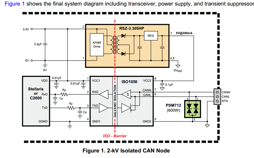
according to the ISOLATED CAN REFERENCE DESIGN.PDF , additional noise filtering of the signal paths between C2000 and ISO1050 is applied through simple R-C-low-pass-filter. the formula is RF * CF = 0.032/fs.

my questions is:

1. if my interest speed of CAN bus is 1Mbps, then how to calculate my interest fs? can you please  tell me one recommend RF and CF for 1Mbps speed.

2.why is so-called R-C-low pass fliter is RF*CF = 0.032/fs. as my known 2*PI*f = 1/RC....

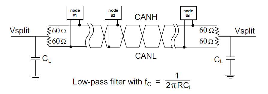
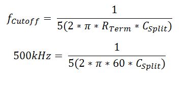
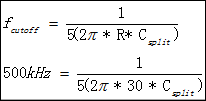
according to the ISO1050 datasheet, in order to improve the electromagnetic emission behavior of network, split terminal resistor is needed. my question is: can you recommend Csplit between two 62ohm resistor?

THX 

BEST REGARDS,


  • Hi Tian,

    These two questions kind of work together. The difference in this formula is, and the one you are used to, is a factor of 5. That is what the application note is recommending that you move out your filter corner frequency by. So your 1MBPS, (which is 500KHz), you should move it out at least to 2.5MHz. The first time I saw this formula I was confused too! I have actually seen these common mode filters with lower corner frequency that the data rate.

    The .032 in the paper is a factor of 5 smaller than the .16 (which is  1/(2*π)). This was written as a constant, as opposed to 5*2*π), with the purpose of creating a simple rule of thumb for picking the filter. The application note is suggesting that you do not set the filter (corner frequency) to the same value of your max data-rate. This is because the way the corner frequency is defined, it is where the filter attenuates the signal to ½ its value. You are correct, a RC low pass filter has a corner frequency at 1/(2*pi*R*C).

    For example, if I wanted to send a 1MHz signal, I would not pick a 1MHz corner frequency filter because then my signal that I wanted to send would leave the filter at half the amplitude it entered. If you move the filter out about a half a decade (factor of 5), the attenuation will not be as severe.

    Thanks,

    John

  • can you show me a curve for relationship for corner frequency  and the real filter? CU'Z i did not catch the information corner frequency and the value of my max data-rate what you've mentioned...

    another problem is :

    can you recommend capacity's  value between two  60 OHM terminal resistor

    thx~

  • Hi Tian,

    I took this picture from the wikipedia cutoff frequency page (http://en.wikipedia.org/wiki/Corner_frequency)

    File:Butterworth response.svg

    The corner frequency, or cutoff frequency as it is called in this page, is where the output of the filter is equal to -3.01dB. This is equivalent to ~1/2 the passband power.

    In terms of the split node capacitor I have seen anywhere between 4.7nF and 100nF used. The corner frequency is equal to:

    So depending on where you want the cutoff frequency of the filter to be, you could vary the value of CL.

    Thanks,

    John

  • thank you so much for your patient and awsome answers.


    accordint to your description, can i regard the factor 5 is an experience number or should i calculate for this by a eqution?

    if so,what's the eqution?

    My best regards.

  • Hi Tian,

    I would use the factor of 5 in the equation. To help explain, let's say you are trying to operate your network at 1 MBPS( which is equal to 500kHz). The equation I am recommending that you use is:

    Thanks,

    John

  • thank you so much~


  • HI John:

    i got another question for your eqution...

    in my opionion the eqution is :

    do i misunderstanding?

  • Hi Tian,

    I have always used 60Ω for my calculations. The reason is there is normally a somewhat significant bus between the two terminations that decouples the two filters. This bus will have series inductance, resistance, and parallel capacitance that will be sitting between the two terminations. Also the noise on each line will only see one half of the 120Ω resistance.

    Also I want to point out that I made a mistake in my statement above. This filter only filters the common mode noise, and therefore it will no filter the CAN differential signal . I apologize for the mistake. I am going to update the response.

    Thanks,

    John

  • John :
     Thanks for your answeres...

    i am confused, if the eqution on how to calculate CAN bus's filter is correct, why is Csplit is 4.7nF to 100nF is existed?

    as my calculation:

    so Csplit is a fixed value.why? i am so confused now....i think  i 've made a  misunderstanding.


    Thanks

    Tian

  • Hi Tian,

    Sorry that this has been confusing. The capacitor value does not have to be fixed. I have seen in range from 4.7nF all the way up to 100nF. This results in the common mode corner frequency ranging from 26.5kHz to 564.4kHz.

    The fixed part of the equation should be the resistor. This is supposed to match the differential-mode characteristic impedance of the cable. This is usually always 120Ω, so people just make the split termination resistors 60Ω each.

    The factor of five is pushing out the filter corner frequency a half a decade. So realistically what it is doing to the equation is making the capacitor value 5 times larger since the resistor value is staying constant. You do not have to use this factor of five if you do not want to. It is a common mode filter and not a differential filter.

    Hope this clears up some of the confusion, I think the applications section could have been written a little clearer.

    Thanks,

    John