Other Parts Discussed in Thread: OMAPL138
Hi,
We have met problems when routing differential USB pairs for the OMAPL138 processor.
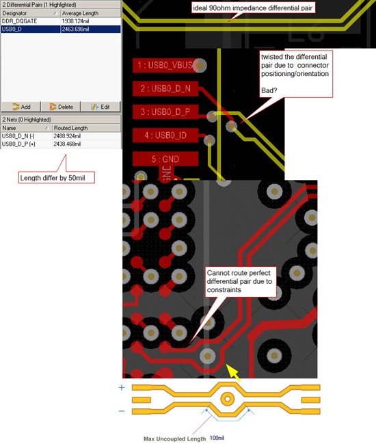
We have followed the USB 2.0 standard to route differential pair with 90Ω differential impedance (upper sub-figure example). However there are two problems we cannot correct due to layout constraints:
1. Because of the relative placement and orientation of the USB header to the processor (and its USB0_D_P and USB0_D_N pins), after having routed the differential pair very close to the header, we had to “twist” them 180 degree with a switching of the layer (see middle sub-figure). This is shown as the yellow differential pair (internal layer) suddenly twisted and emerges on the top layer. Because of the relative position of the two pins on the processor and the header, if we do not “twist” near the header we have to twist somewhere else midway, but this is unavoidable. Would this cause USB fail?
I was wondering that if this causes any problem to high-speed USB communication, can we solve it by lowering USB clock speed, particularly when acting as the USB host?
2. Near the processor there is a length of routing where we cannot parallel the two lines, and this corresponds to what is called “Max Uncoupled Length” by the Protel software (see the bottom sub-figure). How much “uncoupled length” is allowed by the USB 2.0 standard?
3. The final differential pair is not perfectly balanced as shown in the left (panel) of the image in the USB0_D_P is 50mil shorter than USB0_D_N. Can the USB lines still work in this case? If problems encountered when acting as USB host, can we also solve this by lowering USB clock?
Paul


