This thread has been locked.

If you have a related question, please click the "Ask a related question" button in the top right corner. The newly created question will be automatically linked to this question.

DS100BR111 as a SATA Repeater

Hi,

I think I have a problem using the DS100BR111SQE as a SATA Repeater.

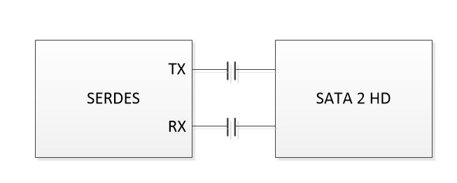
The end point is a regular SATA 2 HD.

This is a block diagram for what is working for me now:


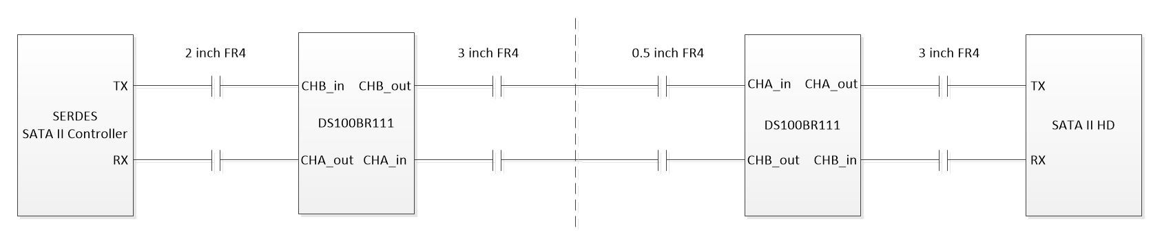
This is a block diagram for what is not working for me:

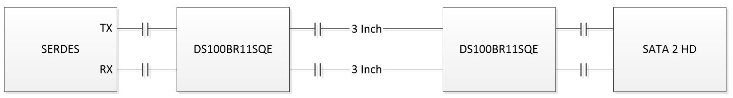
This is a block diagram for what is also not working for me:

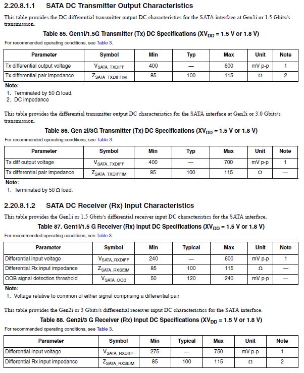
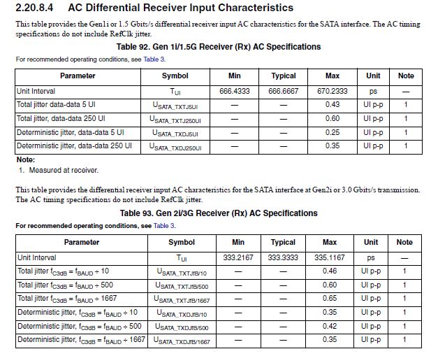
This is the SERDES source characteristics:


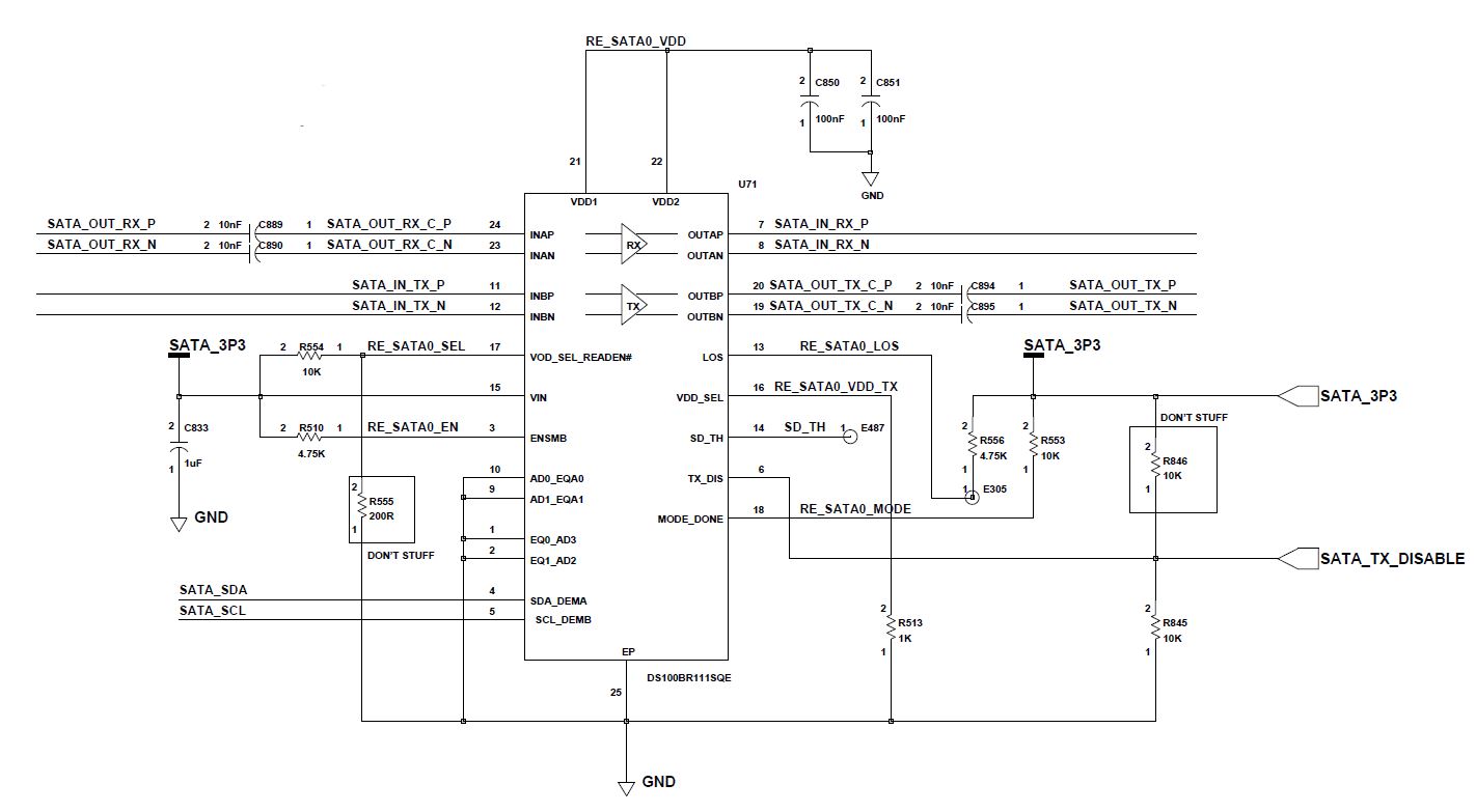
And this is my DS100BR111SQE schematic:

I have access to the I2C bus and I don't think that I need to use it or maybe I wrong?

Please help me to understand what is the problem.


Thanks,

Michael

  • Hi Michael,

    Thanks for providing detailed information about your application. That is always helpful to have. I have a few comments/questions after reviewing your drawings and schematic:

    1. I do recommend the second block diagram (with one set of AC coupling capacitors between the two repeaters) versus the first block diagram (with two sets of AC coupling capacitors between the two repeaters). There is no benefit to having two capacitors in series, and having only one set can often have benefits associated with it, like fewer vias, less overall discontinuities in the transmission path, etc.
    2. Your schematic shows that you are operating the device in what is called "SMBus slave mode" (ENSMB=High), where parameters like output VOD, output de-emphasis, and input EQ are set by I2C registers rather than pin straps. Therefore, in order to set these parameters to suit your application, you must write to registers within the device via I2C. Refer to Table 9 in the datasheet for more information. You may notice that the default value for input EQ is 0x2F under register contol mode (SMBus slave mode), and this setting corresponds to ~24dB of boost at 5GHz. This may be overkill for your application, so this is definitely something you will want to play with.
    3. Your schematic shows VOD_SEL=GND, which forces the SMBus write address for this device, when in SMBus slave mode (i.e. ENSMB=High), to be 0xB0. This is okay because you anyway have the address set to AD[3:0]=4'b000. However, if you had two or more devices on the same I2C bus, then you could not uniquely address them if they both have VOD_SEL=GND, because the would both have the same SMBus write address (0xB0). Refer to the note on page 13 of the datasheet for more information.
    4. The input EQ, output de-emphasis, and output VOD should all be set based on the channel characteristics at the input and output of the device. I see you have noted that between the two devices is 3 inches of PCB. The channel between the SerDes and the repeater, and also between the repeater and the SATA drive will also impact your selection of EQ, VOD, and DE.
    5. It seems a bit unusual to me to have two repeaters placed just 3 inches apart. Is there any particular reason for this?
    Best regards,
    Casey
    If you believe this reply has sufficiently answered your question, please mark it as such by clicking on the 'Yes' button next to "Did this answer the question?"
  • Hi Casey,

    Thanks for reviewing my case.

    Please see more detailed diagram of the system:

    Where the SATA II HD is actually a SATA connector which is connected to a standard SATA cable and from there to the SATA HD...

    Anyway, I've programed both of the repeaters using the I2C to the following configuration:

    [add] : value

    [0x01]: 0xC4

    [0x04]: 0xE3

    [0x08]: 0x04

    [0x0F]: 0x01

    [0x10]: 0xED

    [0x16]: 0x01

    [0x17]: 0xED

    Although this is may not be the optimal configuration for the diagram above, still there is no sign at all from HD.

    Maybe it's VOD voltage level? Maybe because I have two repeaters? (You right about that there is no reason

    for putting two repeaters, but the second one is actually on another board which I didn't desgin...)

    Maybe it's because that on second repeater the CHB is the RX and CHA is the TX while the on the first

    repeater the RX is on the CHA and TX on CHB? (while the IN and OUT directions are OK)?

    Thanks,

    Michael

  • Hi Michael,

    Please add the following to your configuration to disable the slave mode CRC checks, and make this the first register write you do. This allows the subsequent register writes to take effect immediately.

    [add] : value

    [0x06]: 0x18

    I think the VOD is fine, as SATA typically runs with a lower VOD (around 700mVppd) anyway. The DEM is set to -3.5dB by default. That might be slight overkill for your short traces, but I doubt that is causing the problem you're seeing. It wouldn't hurt to lower that to -1.5dB or even 0dB.

    Also, it's probably just a typo in your diagram, but it looks like the SATA HD TX is connected to the second repeater's output, and the SATA HD RX is connected to the second repeater's input. I'm hoping that's just a typo because it would not be the right way to connect the two.

    Regards,

    Casey

  • Hi Casey,

    Thank you alot!

    Regards,

    Michael