


Other Parts Discussed in Thread: SN65HVD232
Hi
Ok. Details. I have a working 5v project running 40MHz, 250kbit/s. I am now making an upgraded 3v3 64MHz 250kbit/s version and it is not working correctly as it generates packet read errors, and the ACK it generates often looks like it is either holding for too long or doing something odd. I have adjusted the Baud rate to match.
I have a CAN packet generator using an MCP2551 to spew out an automated loop of data. Using my existing project with a PIC18F4585 and an MCP2551 (both 5V devices), they talk just fine.
Using my new project with a PIC18F66K80 and a TI SN65HVD232 (same firmware, but running 3v3), I find the CAN packet generator keeps spewing the same packet out as it never receives the ACK back from me. Their grounds are both common and connected. Investigating the CAN signal, I see that with the micro powered down, the CAN bus signal is correct and just waiting for a response. With the micro powered up, I see the CAN bus signal showing the correct offset differential of the 3v3 SN65HVD232 as it tries to ACK, however sometimes there is another signal on top which looks squif.
When I look at the TX coming from the Micro into the CAN controller, i.e. on pin1, "D", I see that there is almost a double bounce on the ack. It drives low for 1x Tbit (4us), releases for 1xTbit, and then drives low again for 6xTbit. During that second time low, the CAN_H/L side of the controller shows a very weird offset voltage shift. In my inexperience with CAN, it looks like 2 devices are trying to drive a zero and between the 5V and the 3v3, it's producing a different voltage level to when the 5V or the 3v3 are driving the line independently.
The more I look at this, the more I think it is likely to be a function of the Microcontroller and not the CAN controller, in which case this should be on the Microchip forums. However, I've already typed it up so the more advise the merrier.
I can't seem to post multiple pictures so will have to reply each time with a picture to show what I mean.
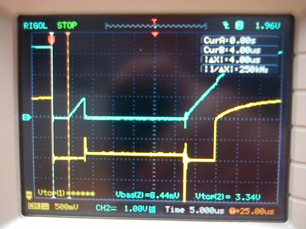
This picture attached shows CH2 (blue) on top as the TX from the Micro into the CAN Controller (Pin1 "D") and CH1 (yellow) on the bottom out the CAN Controller (Pin6 "CANL"). The cursor shows CH2 (blue) driving low for 4us, releasing for 4us, then driving again for 24us. What is it doing but more importantly, why does the CAN line (CH1 (yellow)) go to an intermediate voltage? Is it also trying to drive?
Any ideas would be very welcome.

