This thread has been locked.

If you have a related question, please click the "Ask a related question" button in the top right corner. The newly created question will be automatically linked to this question.

USB design help?

Other Parts Discussed in Thread: TUSB3410, TS3USB221

Hello all,

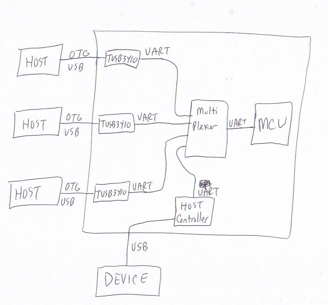
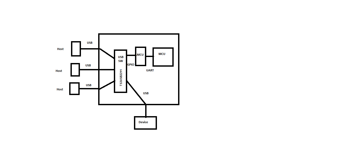
I'm designing a product that will have three USB OTG ports for communicating with 3 portable hosts, and one USB host port for communicating with a peripheral device.  The communication speed isn't critical and its mostly about transferring power.  I'm planning on using the TUSB3410 for converting the OTG USB ports (that connect to portable host devices) to UART so they can interface with a standard MCU.  I'm a little unsure how to handle the host port.  Any suggestions on what chip I can use for the USB-UART conversion on this host port?

Thanks!

John

  • hello John,

        Could you provide a diagram for a better understanding, I got a bit lost on the description.

    Best regards,

    Diego.

  • Attached is a quick sketch.  Basically the missing piece is a USB Host controller that can interface with the MCU via its UART.  The primary purpose of this design is to transfer battery power from the 3 host devices over to the single peripheral device while being able to communicate with each device one at a time.  Any comments/suggestions are much appreciated.

    Thanks,

    John

  • Any feedback?


    Thanks!

    John

  • Hello John,


                    Could you please provide us a little more information about your design?


                    First of all please let me be clear that the TUSB3410 works as a USB to UART bridge (USB Host -> TUSB3410 -> UART)  and not as a UART to USB Bridge (UART Host -> TUSB3410 -> USB Device)


    What we understand is that you are trying to connect a USB-Device to three USB Hosts one at a time, right? If that is correct we believe that you don’t require the TUSB3410 + UART multiplexer for your design and it’s better if you replace those devices with a USB Switch (we recommend you the TS3USB221 http://www.ti.com/lit/ds/symlink/ts3usb221.pdf) and your MCU can control the switch behavior.


    Please note that the TS3USBB221 is a 2:1 USB switch so you will require to connect two TS3USBB221 in cascade to create a 3:1 USB switch.   

    Here is a quick diagram of our recommendations.


    Regards,

    Roberto.

  • Hi Roberto,

    Thanks for the great suggestion. 

    I'm designing a product for a client that is designed to take charge from up to 3 phones and transfer that charge to a 4th phone.  The product will communicate with each phone so as to monitor the charging process to ensure no phones are completely discharged.  So the product needs to have 3 device ports and one host port. 

    The three phones that provide charge will act as hosts (using OTG) and the 4th phone acts as a device.  I'd like to have it compatible with USB Battery Charging Spec 1.2.  I was planning on using the TI24392 for detecting the charging capabilities of each host. 

    Where are the USB transceivers in your design, after the USB switch I assume?  Your diagram shows the TS3USB221 outputing data as GPIO, with a second MCU converting it to UART.  I don't understand this.  It seems to me that you need a TUSB3410 between the switch and the MCU to convert from USB to UART?

    Thanks!

    John

  • Actually I'm now leaning toward using a MCU with USB capabilities so no need to convert to UART.  Now mainly wondering how to handle the host port.  Host controllers are quite expensive as is any MCU that has USB hosting ability.  Any suggestions?


    Thanks,

    John

  • Any updates from anyone on my questions above?


    Thank you!!

    John

  • Any suggestions from any TI app engineers in regards to my questions above?  I really appreciate any suggestions!


    Thanks so much!!

    John Teel
     (former TI IC designer)

  • Hello John,

     The suggested switch will help you to connect the 4th phone to each one of the other 3 phones one by one. The GPIO signals are only to control the USB SWITCH. You can use the MCU of your choice to control the GPIO signals.

     Regards,

     Roberto.