


Other Parts Discussed in Thread: DP83620
Hello,
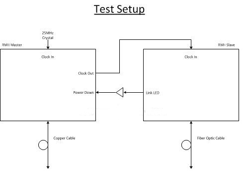
Customer is using 2, DP83620s for a copper to fiber link per the attached. The copper link is always connected but the fiber link can be disconnected/reconnected and the phy at the other end of the copper link needs to know this. Use of the LED_LINK as shown acts as the Fiber Link Status indicator to the remote copper phy. Customer has a few DP83620 questions for this application (below). I provided explanations in red below but feel free to add comments or verification.
- Would it make any more sense to use the reset pin of the PHY as opposed to the Power Down pin? [jp] RESET_N causes all internal registers to return to their default state. PWRDOWN just powers down the PHY but leaves the register bit settings intact so PWRDOWN looks like the right control to use.
- I wanted to get confirmation that the LED_LINK (pin 28) was the appropriate pin to use to convey to our system the link status from the fiber PHY. The other signal that we had considered was the CRS (pin 40). The carrier sense seems to be more related to activity detect than link status. Would you agree that the appropriate signal to use is LED_LINK? [jp] Yes, LED_LINK should be used for the reasons you stated.
- If you could shed any more insight as to what actually has to happen for the LED_LINK signal to be both asserted and de-asserted that would be helpful. Specifically the data sheet states that the signal is on when “Link is Good”. What exactly signifies that the link is good? [jp] See Section “5.6 LED INTERFACE” on pgs. 35 and 36 of the Data Sheet for a complete description of LED_LINK and assertion/de-assertion conditions. Please let us know if you have additional questions.
