This thread has been locked.

If you have a related question, please click the "Ask a related question" button in the top right corner. The newly created question will be automatically linked to this question.

SN65LVELT23D AC Output

I am using the SN65LVELT23D chip to try change a pulsing LVPECL signal to a pulsing LVTTL signal. The arriving differential signal is an output from a comparator, where the signal changes between ~1.7 and 2.6V. (I am using both available differential pairs for the same purpose.

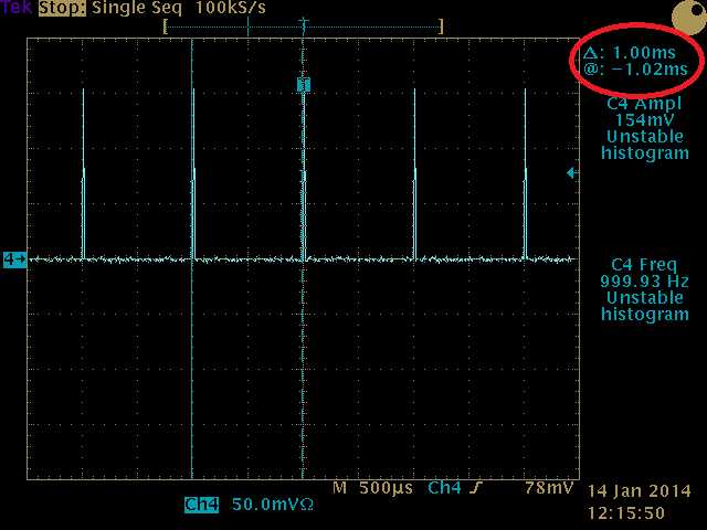
However, somehow from the output channels all I am getting is an AC waveform ~25 MHz, with the voltage oscillating between ~0.6 to 2.4V. This signal is on only when the comparator is pulsing (fully on 100% of the time, not pulsing along with the comparator output). No other pins have this sort of waveform on them, and the pulsing input only consists of 1 us pulses at a frequency of ~1000 Hz. Have I gone terribly wrong somewhere along the line and broken the chip, or am I doing something fundamentally wrong? Where is the 25 MHz signal coming from? This is happening when a 470 Ohm resistance is connected as the load for testing purposes.

Thanks,

Morten

  • Hi Morten

    As you described, I think that you connect the output of comparator with the input of SN65LVELT23D directly(DC couple). right??

    I am not so familiar with comparator. As far as I know, the output of comparator swings near the rail. So could you tell me the part number of the comparator that I can get more information. If not DC couple, please show how to connect, too.

    Hi-speed circuit is easy to be a unstable circuit. If you can tell more details about your layout, grounding, power decoupling, maybe it will help.

    Regards

    Michael

  •  

    Hi Morten,

    I use our EVM boards to simulate your condition and result. Input 1KHz 1us width pulse and the ouput is proper.

    So I think the chip can work for what you want.

    Can you check the input match network of resistors? Some guys may not set it properly. The EVM use 130 and 82 ohms resistors as voltage divider and match network.

    3757.SN65ELT23.pdf

    Michael


  • Yes, as far as the comparator (ADCMP552) is concerned, it is DC coupled. I have 10 uF and 10 nF capacitors for decoupling the 3.3V supply into the SN65LVEL chip. 

    After further testing with a different brand of chip, with basically the same performance (MC100LVELT23DG) I am sure that it is now a circuit issue, as I am getting the same awkward performance, but I am unsure how it could possibly be.

    Apologies, the results stated above are slightly off, as I have had a more careful look at the output, and it is in fact performing as expected on a logic high, and only oscillating on a logic low. A single switch to a logic low, with no pulsing, seems to behave as expected, with a logic low output. However, if it is kept at a logic low after a period of pulsing, it remains in the oscillating state, with no switch to a logic low until the input states are slowly toggled.

  • So I've found out the issue... I had assumed the chip's internal pullup and pulldown resistors were LVPECL standard but yes, I now realise I needed those external terminations.

    Thanks for the help!

    Morten

  • Hi Morten,

    It is my pleasure that you can solve the problem.

    Michael