This thread has been locked.

If you have a related question, please click the "Ask a related question" button in the top right corner. The newly created question will be automatically linked to this question.

Bus fault in redundant configuration

Other Parts Discussed in Thread: SN65HVD257

Dear all,

In a safety application we are using SN65HVD257 CAN drivers in a Redundant Physical Layer CAN Network Topology as indicated in the relevant data sheet (see figure attached). The number of our nodes is variable between 2 and 13, with a 500 KHz bit rate.

We have encountered the following problem:

When only one of the two wires of a CAN BUS is cut, it sometimes happens that a series of random errors makes communication on both buses impossible. If, on the other hand, both the wires of a bus are cut, no problem occurs.No problem occurs also if one bus wire is cut in a position farther from the node, or with a larger number of nodes connected on the buses.

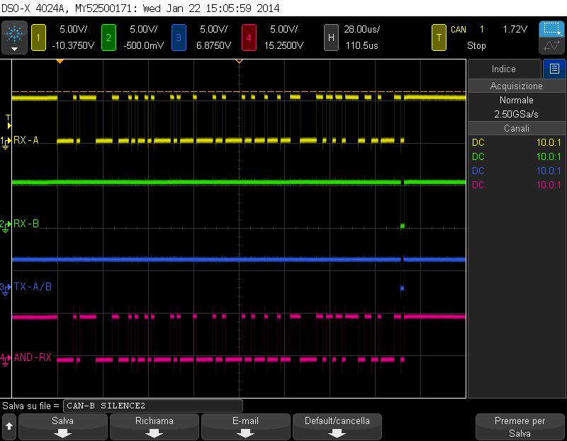
We have noticed that if the driver involved by the cut is forced to silent mode by the CPU, correct communication is recovered.

Is this behavior normal???   If so, can you suggest a sequence of diagnostic software operations to be carried out for unequivocal identification of the driver affected by the cut and its consequent forcing to silent?

Best Regards.

Livio

5123.RCAN.pdf 

  • Hi Livio,

    Since there are two completely separate physical layers, they should operate independently from each other. Therefore, an error on one should only momentarily cause an error on the other.

    Even if one bus got stuck in a dominant state the bus would only block communication on the combined RXD pin for RXD dominant timeout, before the transceiver with the fault would release the RXD pin to a high state (idle). It looks like you are handling the faults individually instead of combining them with an XOR gate. Would you be able to share a couple screenshots of different combinations of signals when the issue is occurring (you most likely will not be able to show both TXD signals, both RXD signals, the Fault lines and the bus signals on one scope, unless you happen to have a mixed signal scope available).

    Thanks,

    John

  • Dear John,

    Thanks for your response.

    As you can see from the attached screenshots, the problem appear only with a single cut failure near the module. In this case (screenshot-1), strangely the RX-B signal which is interrupted is present at RX pin of the driver, but the transmission in this condition fails.


    Screenshot-1


    If I force the driver B in silent mode (screenshot-2) all is OK. The driver B RX signal is still present but it cannot transmit any bit because it is in silent mode.


    Screenshot-2


    Also if I do a single cut, away from the module all is OK (screenshot-3) because in this case the RX signal on driver B is  correctly not present.


    Screenshot-3


    Here you can see the schematic of my circuit.


    8103.CAN SCHEMATIC.pdf


    Regards


    Livio    


  • Hi Livio,

    Thanks for sharing the schematic and all the screenshots! This is very helpful.

    One guess that I have is that the local node, with the cut wire, is missing the ACK delimiter bit. When it expects to see a recessive level, and instead sees a dominant level, it will send an error to the bus blocking communication.

    If you are not familiar with the standard Data Frame in CAN, it is made up of several fields, the last three being a CRC field for error checking, an acknowledgment field so the sending node can verify if the other nodes on the network received a valid message, and the end of field frame used for signaling if a frame needs to be resent, or if a node is overloaded.

    The acknowledgment field, is where I think the issue is occurring. In this field the sending node sends a recessive bit to the bus, and listens for a dominant bit to be sent to the bus from all the receiving nodes. This bit is followed directly by a recessive delimiter bit. It is the job of every listening node on the network to run a CRC check and compare it to the CRC check that is sent by the sending node. If they match, the receiving node sends a dominant bit, if they do not, then the receiving nodes send a recessive bit. Under normal circumstances many nodes will be sending a dominant bit at the exact same time verifying a valid message was sent.

    In networks with lots of nodes all driving the bus in parallel a much more dominant signal will be seen on the bus and all the capacitances on the bus will be charged to a higher level. This results in a longer decay time for the bus to get back to the recessive level. Since only a single bit time is allotted for this to happen, it is very common for this bit to be the cause of errors on a CAN bus.

    To further explain what I think is happening with some math, a normal bus with proper termination the differential resistance is ~60Ω, which is the driving force bringing the bus back to a recessive state.  If the network has between 10 and 100 nodes, and we estimate that each node contributes 100pF of single ended capacitance to the network, then there will be a total of 1nF to 10nF of capacitance on CANH and CANL. This results in a time constant that ranges from 60ns to 600ns (60Ω* 1nF or 10nF).

    Now if we disconnect on of the CAN bus wires from the network, it will no longer have the termination resistance driving it back to the 2.5 volts recessive state. This could result in it taking more time for the voltage on this bus pin to decay. If we take the 100pF of single ended capacitance again, with only the internal 15kΩ resistance driving it back to recessive state, this results in a time constant of 1.5µs. This results in it taking 2.5 to 25 times longer for the bus voltage to decay.

    I think if you take a screenshot of CANH and CANL on the transceiver that has the cut wire, we may be able to see if this is the cause of the issue. Hope this helps, please let me know if you have any questions.

    Thanks,

    John

  • Hi John,

    I also thought that the problem was due to the parasitic capacitances and the different load.
     
    Now my question is:
    How can I repair to this problems??
    I thought to implement a diagnostic routine in all the node wich regularly send a diagnostic message.
    When the sending node detect a trasmission error, the CPU switch the driver-A in silent mode and try to re-transmit the diagnostic message. If the trasmission error persist, the CPU switch the driver-A in normal mode and than the driver-B in silent mode.
    As a result of the test performed it seems that with the driver with the cut wire in silent mode no problem occurs during the comunication on both buses.
    Can be this solution correct ???
     
    Best Regards
     
    Livio
         
  • Hi Livio,

    Your thought process is exactly what you are going to have to do when an error is detected.

    You will need to have some edge triggered software routine that runs when an error is detected on either Error output pin of either transceiver, or what we refer to as Error3, which is the logical XOR of both individual RXD signals from the two transceivers in the redundant network.

    Once an error on any of these (possibly) three inputs into the micro occurs run a series of events to try and diagnose what type of error has occurred.

    The fault pins only tell you RXD DTO, TXD DTO, under voltage or thermal shutdown.

    The XOR of the RXD signals tells you if the RXD signals are different (with some filter to allow for bus mismatching).

    Through transmitting and receiving together, transmitting and receiving individually (through the use of silent mode), you should be able to figure out which bus has the error, and where on the bus it is.

    Have you looked at the User Guide for the device yet?

    http://www.ti.com/lit/pdf/sllu172

    Thanks,

    John

  • Hi John,

    Thanks for your response.

    Now all is clear.

    Regards

    Livio