This thread has been locked.

If you have a related question, please click the "Ask a related question" button in the top right corner. The newly created question will be automatically linked to this question.

DS110DF410 - Eye monitor, eye position

Guru 19785 points

Other Parts Discussed in Thread: ALP, DS110DF410, DS110DF410EVM, DS110DF410EVK

Hi Team,

Please tell me about the EOM.

My customer and I are displaying the eye pattern in the EXCEL sheet, by reading register 0x25/0x26.
When I build up the eye pattern, the eye is not in the center, a little bit shifted to the right.

How can you read the data which eye pattern is positioned in the center ?
Is there any setting ?


Best Regards,
Kawai

  • Hi Kawai-san,

    Thanks for posting. Unfortunately, there is not a quick solution way to center the eye diagram with a specific register setting.

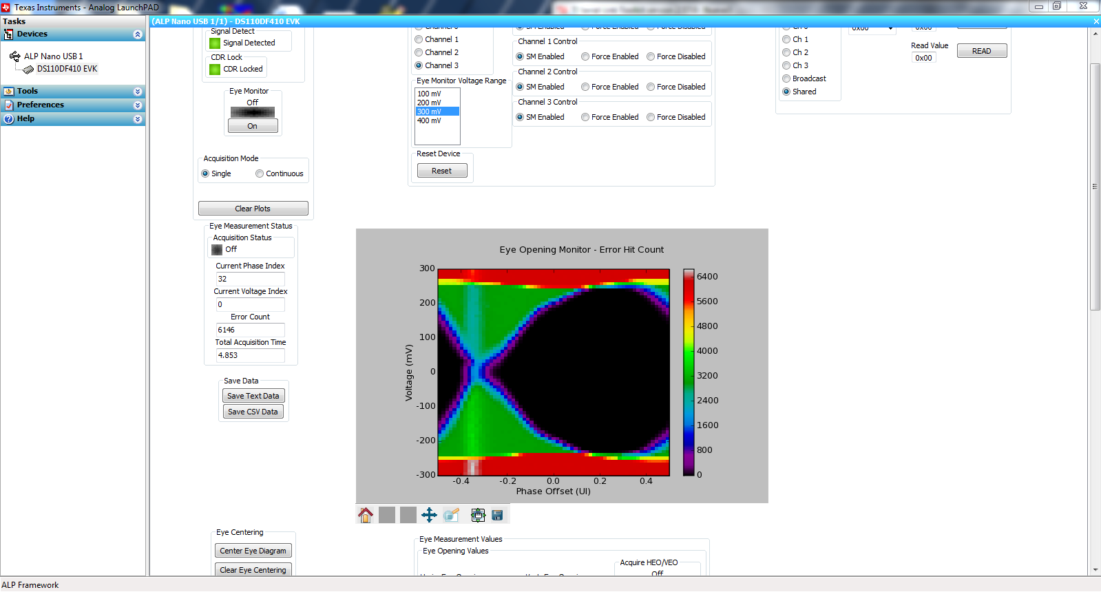
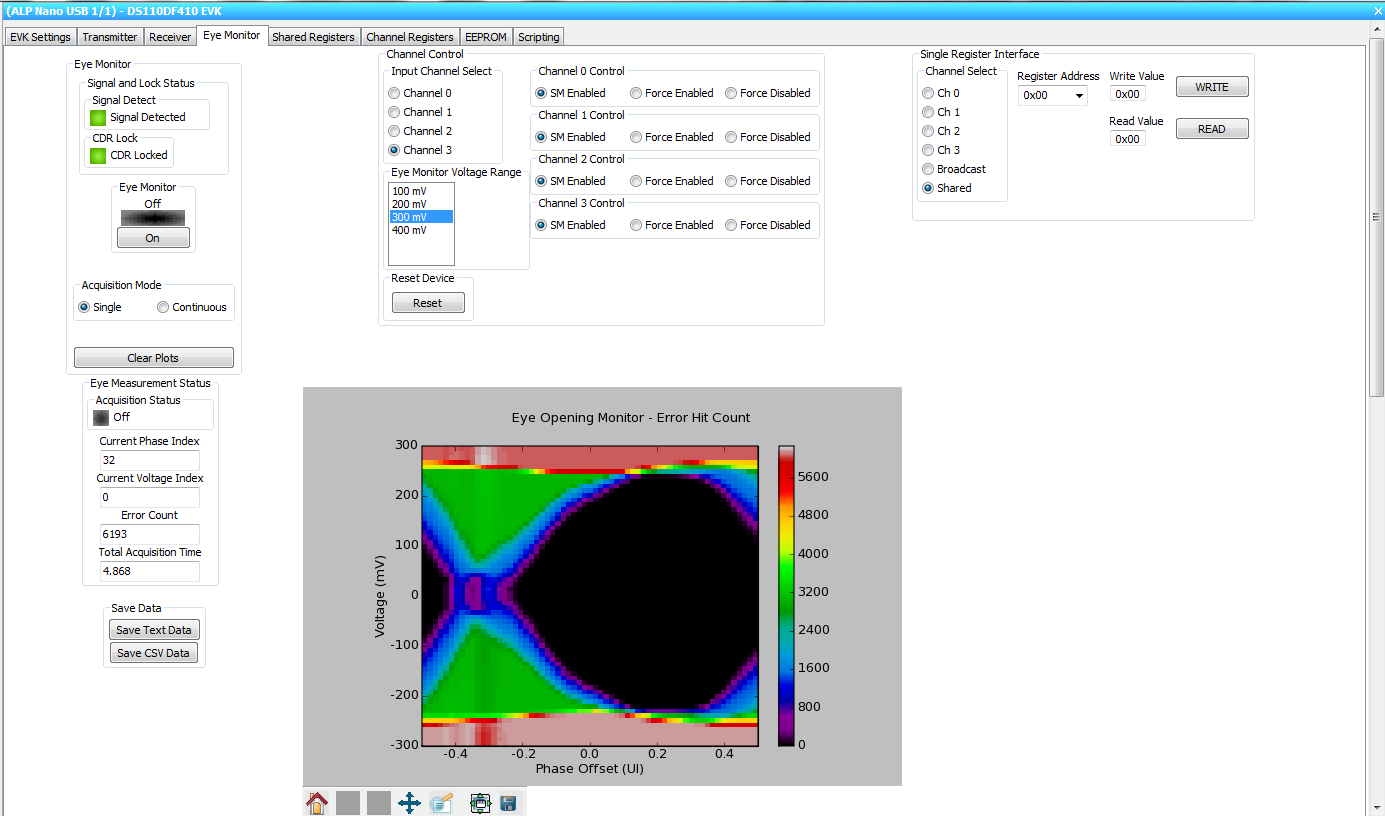
    In the DS110DF410 ALP GUI profile, there is a functionality to "Center Eye Diagram". The Eye Diagram is often not centered at 0.0 UI phase offset, because the electrical lengths of the paths between the two detectors of the DS110DF410 retimer are not precisely integer multiples of 1 UI. The ability to "Center Eye Diagram" comes from post-processing the data to offset the eye by the correct amount of UI.

    I will need a few days to look into the centering algorithm that is programmed into ALP in hopes that it can provide some insight to suggest how you can center your eye pattern. I hope to have a more detailed response next week.

    Thanks,

    Michael

  • Hi Michael-san,

    Thanks for replying.

    Do you mean that the position where center of the eye appears would be in random ?

    Please let us know when you have got the information how ALP is centering the EYE.
    Maybe it is just shifting the error count (column) in horizontal direction.

     We are grateful for your help.

    Best Regards,
    Kawai 

  • Hi Michael-san,

    Please let me ask you one more about EYE position.

    Our customer had read the register and built the EYE diagram such as below.

    The center of the vertical position of the Eye is shifted down side.

    Would their be an EYE diagram such as above, or is it a mistake in the reading procedure ?

    Best Regards,
    Kawai

  • Hi Kawai-san,

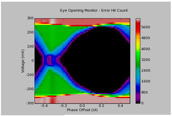
    When the eye monitor is used, the retimer CDR acquires lock by locating a point in time where the average bit transitions occur. This point in time is assumed to be the equivalent of the 0.5UI point, and it is ideally where PDAC (variable-phase clock) = 0. (Note that there are 64 evenly spaced phases that make up one UI.) However, a perfectly located average bit transition location rarely occurs because there is a small delay between the input signal and where the CDR clock is sampling, resulting in the eye appearing offset. For example, it may be found that the average bit transition happens somewhere around PDAC = 20.

    Having located the average bit transition point in time, the center of the eye is assumed to be roughly 30-31 phase divisions afterward. In an ideal eye monitor, this would mean that on Column 32, the actual 0.0UI point would be perfectly in the center. However, in the second example where PDAC = 20 at the average bit transition location, the actual 0.0UI point would be located around Column 50.

    When the eye monitor is measured, the device initially assumes the perfect scenario where the eye center is located around Column 32 and that there are approximately 30-31 columns on each side of the "eye center" to fill with bit error data. However, in imperfect cases like the second example, if we started with Column 50 and assume that there are 30-31 columns to fill on the right, we will hit Column 63 and still have 16-17 columns left to fill. These extra columns that cannot fit on the end are then populated on the front few columns instead. If you look at the screenshot of PRBS-31 data running from a 10.3125Gbps source, you can see that this horizontal offset leads to extra columns beyond Column 63 being placed in the first few columns.


    Having an internal eye monitor that is not centered is normal. As of now, ALP's algorithm appears to be locked in a .dll file, so it will take us some time to uncover exactly how ALP is recentering the diagram. However, it appears that if the retimer is conscience of which PDAC setting the average bit transition time occurred, then the eye monitor simply performs a horizontal shift so that the eye appears centered again.

    The downward shift from your latest post seems strange. If the input signal is a perfect differential signal, the eye monitor should be observing a signal centered around 0mV. Are the inputs AC coupled? The down shift could possibly come from a larger magnitude negative voltage swing than positive voltage swing. Before suspecting anything wrong with the eye monitor reading procedure, I'd double-check the circuit first.

    Thanks,

    Michael

  • Michael-san,

    Thank you for the detail explanation. We really appreciate for your help.

    [Question]
    For the bit transition point, can you say that it would always appear at the same point  if they use the same board ?

    *I've been using the DS110DF410EVM. I know that the ALP always show the bit transition point at around -0.4UI point in the horizontal axis. 

    [Qustion]
    If you want to use the GUI(ALP) to show the eye pattern of the device on customer board, you would need to interface PC through USB. 

    (CASE 1) Using DS110DF410 EVM
    In this case, can you monitor the eye pattern by just connecting the taget device SMBus lines (SDA/SCL/GND) to EVM SMBus lines ?
    I think you can choose the device on the SMBus line by setting the target SMBus address through ALP.
    If there is any restrictions please let me know.

    (CASE 2) No EVM
    Is it possible to use ALP without the EVM ?
    I think the driver is only supporting the EVM, which means that one would need to  build driver if they would use other micro controller to interface SMBsu to USB.

    Best Regards,
    Kawai

  • Hi Kawai-san,

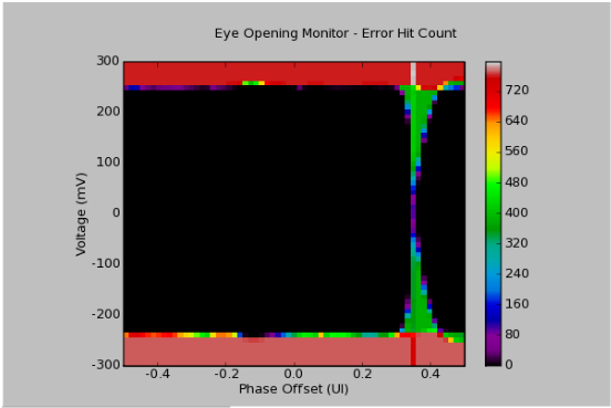
    The bit transition point should appear at the same point if the same board is used at the same data rate. Changing data rates result in a different time where the bit transition is caught after the delay. For example, compare the eye at 10.3125Gbps v. 1.25Gbps:

    10.3125Gbps Bit Transition for EOM, Non-Centered

    1.25Gbps Bit Transition for EOM, Non-Centered

    If you want to use the GUI (ALP) to show the eye pattern of the device, you are correct in assuming that you will need to interface the PC through USB.

    Case 1: I have tried using the DS110DF410EVM to control the registers of another DS110DF410EVM, and had some trouble doing so, because if you plug the mini-USB into the EVM, ALP will not allow you to select the SMBus address.

    Case 2: I have found that you can select the target address by connecting the SMBus lines to a SPA dongle instead of a DS110DF410EVM board. You can use the ALP without the EVM as long as you have access to the SCL/SDA/GND lines on the test device and connect them to an interface like the SPA dongle. If they use another microcontroller, then the driver will need to be rebuilt.

    Thanks,

    Michael

  • Michael-san,

    Thank you for the answer. I under stood.

    Please tell me a little bit more about how to show the eye pattern using the GUI, with the customer board.

    In the customer application, there will be several DS110DF410 devices on the SMBus line.
    They are considering to use ALP to show Eye pattern on PC.

    [Question]
    I understood that the GUI cannot choose the SMBsu address.
    Does this mean that there is no way to use GUI on customer boards with several DF410 on SMBus line ?

    [Question about CASE2]
    Could you please tell me the detail connection ? I beleive it is below.

    DS110DF410EVM ----------> SPA Dongle ----------> PC
                                       SMBus                             USB

    I have tried with my SPA dongle and the EVM, but it did not work. Do you need any programming or setting ?
    I appreciate if you could tell us the direction how to do this.

    [Question]
    In the GUI, "Tools" ---> "Device Profiles", I can find the profile named "DS110DF410Standalone  DS110DF410 Retimer".  In demo mode, it seems that this could choose SMBus address.

    What is this profile and when is this used ?
    Is there any way to use this ?

    [Question]
    If customer wants to buy SAP Dongle, how can we order this board ?

    Thanks and Best Regards,
    Kawai

  • Hi Kawai-san,

    1. If all the DS110DF410 devices are in slave mode, share the same SMBus line, and have different device addresses, you should be able to use the GUI to communicate with different retimers. I am assuming that you have access to the SDA/SCL/GND pins of the SMBus line and can connect the SPA dongle to them.

    In my previous message, I found that if you connected the mini-USB to the DS110DF410EVM and tried using the SMBus pins (located on J86) instead of the SPA dongle to control another DS110DF410, I wasn't able to select a different retimer device address.

    2. The connection you show for the SPA dongle and the PC look correct. I think one reason that it may not be working is because the SPA dongle is not flashed with the right .hex code. In order to do that, you will need to run Atmel FLIP Utility and flash the MCU on the SPA dongle with the "spa_DS110DF410_Standalone.hex". This hex file can be found either be looking in ALP's Driver folder or the DS110DF410Standalone profile folder. After that, the SPA dongle should be able to work when you connect the SPA dongle and set the EEPROM setup to DS110DF410Standalone. I have attached directions of how to do this.

    4606.Installing Atmel Flip Utility on Windows 7.docx

    3. The "DS110DF410 DS110DF410EVK" profile works when you plug in the mini-USB directly into the DS110DF410EVM. The "DS110DF410Standalone DS110DF410 Retimer" profile uses the SPA dongle to talk to the DS110DF410EVM, and you can communicate with the DS110DF410EVM this way by connecting the SCL/SDA/GND pins directly from the SPA dongle to the corresponding pins on J86 instead of plugging in the mini-USB on the edge of the EVM.

    Since you can select the SMBus address like you mentioned with the DS110DF410Standalone profile, I believe you should be able to connect the SCL/SDA/GND pins from the SPA dongle to the SMBus lines of your customer system to access multiple retimers with the DS110DF410Standalone profile.

    4. Unfortunately, the SPA dongle is not available via the TI eStore at the moment. Please contact me offline at m-lu@ti.com to discuss more about the SPA dongle.

    Thanks,

    Michael

  • Hi Michael-san,

    Thanks for your great support !!
    Now I'm clear.

    I will try using the tool for the SPA dongle tomorrow.
    Please let me ask you when I face some trouble.

    Best Regards,
    Kawai

  • Hi Kawai-san,

    Great! Good luck! :-)

    Thanks,

    Michael