This thread has been locked.

If you have a related question, please click the "Ask a related question" button in the top right corner. The newly created question will be automatically linked to this question.

DS110DF410 - Default Register Map

Guru 19785 points
Other Parts Discussed in Thread: DS110DF410, DS110DF111, DS100DF410

Hi Team,

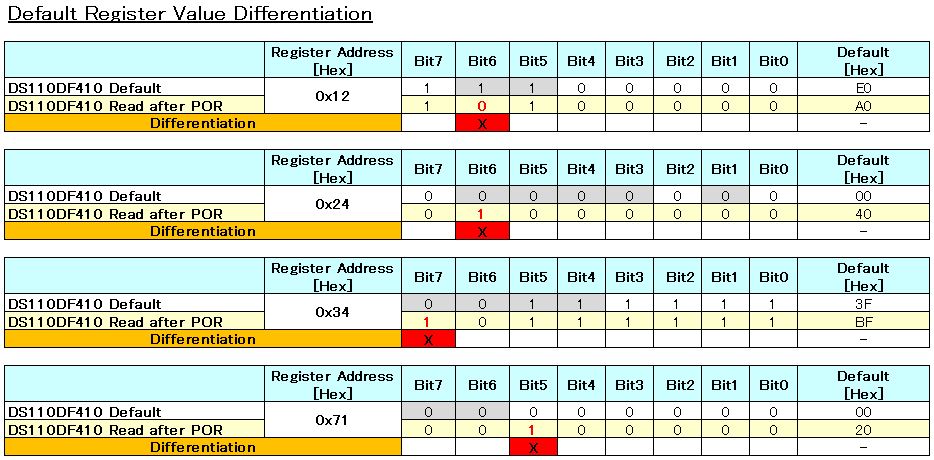
Could you please provide us the full register map for DS110DF410 ?

We would like to have the 8bit default value for each register address like DS110DF111 datasheet.
Below is the register map of DS110DF111.

However, for example, in DS110DF410 register map, there are many blind bit information.
 Address 0x09 does not show default bit information for bit 6,4,3,1,0. 
 Address 0x15 does not show default bit information for bit 5,4,3.

Our customer needs to shorten their programming time.
They will use this default value information when programming each settings.

Best Regards,
Kawai

  • Hi Kawai,


    I apologize that nobody has responded to your question but somebody will be looking into this and will reply shortly.

    Regards,

    Michael Peffers

    Analog Application Engineer

  • Hi Kawai,

    Michael Hinh is the Application engineer of this part. He will send you the information on Feb 3 when he returns to office.

    regards,

    TK

  • Hi Michael-san, TK-san,

    Thank you for your reply.

    I will wait for the information from Michael Hinh-san.

    We are grateful for your help.

    Best Regards,
    Kawai

  • Hi Kawai-san,

    Attach is the register information with the default values for the DS110DF410.

    Regards,

    Michael

    2450.DS110DF410_register_default.xlsx

  • Hi Michael-san,

    Thanks for the information. This will help us very much.

    Best Regards,
    Kawai

  • Mike:


    I am the CTO of North East Systems Associates, Inc.  (NESA) we need design support for the DS110DF410.

    NESA is designing a test card for backplane performance measurements using the DS100DF410 to provide equalization imporovement in the protocol agnostic capture of eye-diagram performance..  We already have passive cards which perform a similar function with bench level instrumentation such as the Agilent 86100C. As a member of the Ethernet 802.3 committee, I know that the standard qualification measurements are in the frequency domain, but my clients want to see an eye-diagram.  I am using the test card schematic as the basis of our design.

    Is this the best TI chip to use for 10 - 12.5 Gbps measurements?.  Is there a wider chip so that more than a single channel can be captured?   Are there native xxx.dsn OrCad schematics available to simplify the schematic design process?

    Thanks -


    ed sayre,   esayre@nesa.com

  • How do I get design support for the DS110F410EVK in the Boston area?

    ed sayre

    [C[ 978-314-4940,  [T] 781-837-9088  esayre@nesa.com

  • Hi Ed,

    Michael will contact you through email.

    Regards,

    TK Chin

  • Hi Michael-san,

    Could you please let me ask about  the default register map which you had attached in the last post ?

    Our customer and I had read the register data of the device after POR(Power on Reset), but there were some differentiation.

    Could you tell us what these bits below means and whether there is any problem when they are changed to the default bit ?

    Address 0x12 bit6
    Address 0x24 bit6
    Address 0x34 bit7
    Address 0x71 bit5

    Best Regards,
    Kawai

  • Hi Kawai-San,

    These register are internal confidential state machine flags.

    Please note content of Register 0x02 which indicates the overall reclocker status. Would it be possible if you could please read register 0x02 CDR status register and explain what is the customer issue or problem.

    Regards,,nasser


  • Hi Kawai-san,

    The bits are read only and depending on the device status condition the bits are set by the digital state machine.

    Customer should ignore and not try to change these bits.

    Regards,

    Michael

  • Hi Nasser-san, Michael-san

    Thanks for your comments. I understood that thses four bits are all read only bits.

    In the case of writing this read only bit to the default value, would there be any problem ?
    For example, customer writes the default value for Register 0x24 bit6 = 0 when they use the EOM.

    I understand that it is best to ignore and not change these bits, but our customer had been already fixed their program and is difficult to change.
    As these bits are READ ONLY bit , I beleive that the change in these bits would not have an adverse impact to the device operation.  

    Best Regards,
    Kawai