


Other Parts Discussed in Thread: PCF8575, LM3S6965
I'm using PCF8575 with LM3S6965 via bitbanging I2C. I read the first byte very accurately but having a problem reading the second one. I always get 0xff for the second. What I'm actually doing is that I first write to the port a random value like 0x7988 then the reading interrupt is activated to supposedly read the same value.
This is a piece of the code i'm running, while the writing occurs flawlessly I haven't it mentioned here:
int main(void)
{
 	SysCtlLDOSet(SYSCTL_LDO_2_75V);

	// Set the clocking 50MHz to run directly from the crystal.
	//
	SysCtlClockSet(SYSCTL_SYSDIV_4 | SYSCTL_USE_PLL | SYSCTL_OSC_MAIN | SYSCTL_XTAL_7_37MHZ);

	IOX_Init();
	WriteByteToIOX(0x7988, 0x42);

	while(1);
}


void IOX_Init()
{
	SysCtlPeripheralEnable(SYSCTL_PERIPH_GPIOA | SYSCTL_PERIPH_GPIOC);

	//SCL PA6 & SDA PA3 pins
	GPIOPadConfigSet(GPIO_PORTA_BASE, (GPIO_PIN_3 | GPIO_PIN_6), GPIO_STRENGTH_4MA, GPIO_PIN_TYPE_OD);
	GPIODirModeSet(GPIO_PORTA_BASE, (GPIO_PIN_3 | GPIO_PIN_6), GPIO_DIR_MODE_OUT);
	GPIOPinWrite(GPIO_PORTA_BASE, GPIO_PIN_3, GPIO_PIN_3);
	GPIOPinWrite(GPIO_PORTA_BASE, GPIO_PIN_6, GPIO_PIN_6);

	//Interface3GPIO3==> interrupt pin
       //No external pull up
	GPIOPadConfigSet(GPIO_PORTC_BASE, GPIO_PIN_4, GPIO_STRENGTH_4MA, GPIO_PIN_TYPE_STD_WPU);

	GPIOIntTypeSet(GPIO_PORTC_BASE, GPIO_PIN_4, GPIO_BOTH_EDGES);
	GPIOPinIntEnable(GPIO_PORTC_BASE, GPIO_PIN_4);
	GPIOPortIntRegister(GPIO_PORTC_BASE, &ReadHandler);
}


void StartCondition(void)
{
	//Set SDA and SCL HIGH at the same time
	GPIOPinWrite(GPIO_PORTA_BASE, GPIO_PIN_3, GPIO_PIN_3);
	GPIOPinWrite(GPIO_PORTA_BASE, GPIO_PIN_6, GPIO_PIN_6);

	halMcuWaitUs(30); //min 4.7usec

	//Drive SDA LOW
	GPIOPinWrite(GPIO_PORTA_BASE, GPIO_PIN_3, 0);

	halMcuWaitUs(30); //min 4usec

	//Drive SCL LOW
	GPIOPinWrite(GPIO_PORTA_BASE, GPIO_PIN_6, 0);

	halMcuWaitUs(30);
}

void StopCondition(void)
{
	GPIODirModeSet(GPIO_PORTA_BASE, GPIO_PIN_3, GPIO_DIR_MODE_OUT);
	GPIOPadConfigSet(GPIO_PORTA_BASE, GPIO_PIN_3, GPIO_STRENGTH_4MA, GPIO_PIN_TYPE_OD);

	//Set SDA and SCL LOW at the same time
	GPIOPinWrite(GPIO_PORTA_BASE, GPIO_PIN_3, 0);
	GPIOPinWrite(GPIO_PORTA_BASE, GPIO_PIN_6, 0);

	halMcuWaitUs(30);

	//Drive SCL HIGH
	GPIOPinWrite(GPIO_PORTA_BASE, GPIO_PIN_6, GPIO_PIN_6);

	halMcuWaitUs(30);

	//Drive SDA HIGH
	GPIOPinWrite(GPIO_PORTA_BASE, GPIO_PIN_3, GPIO_PIN_3);

	halMcuWaitUs(30);

	//Drive SCL LOW
	GPIOPinWrite(GPIO_PORTA_BASE, GPIO_PIN_6, 0);
}

void ReadHandler(void)
{
	unsigned int data = 0;
	//Clear INT bit
	GPIOPinIntClear(GPIO_PORTC_BASE, GPIO_PIN_4);

	data=ReadByteFromIOX(0x43);
}


unsigned int ReadByteFromIOX(unsigned char readslaveadd)
{
	unsigned char x;
	unsigned int newdata = 0;
	unsigned char i;

	StartCondition();

	for(i = 0; i < 8; i++)
	{
		WriteBitToIOX(readslaveadd & 0x80);
		readslaveadd <<= 1;
	}

	GPIOPadConfigSet(GPIO_PORTA_BASE, GPIO_PIN_3, GPIO_STRENGTH_4MA, GPIO_PIN_TYPE_STD);
	GPIODirModeSet(GPIO_PORTA_BASE, GPIO_PIN_3, GPIO_DIR_MODE_IN);

	//Handle the ACK
	//Drive SCL LOW
	GPIOPinWrite(GPIO_PORTA_BASE, GPIO_PIN_6, 0);
	halMcuWaitUs(60);

	//Drive SCL HIGH
	GPIOPinWrite(GPIO_PORTA_BASE, GPIO_PIN_6, GPIO_PIN_6);
	halMcuWaitUs(60);

	for (i = 0; i < 8; i++)
	{
		x = ReadBitFromIOX();
		if(x)
		{
			newdata <<= 1;
			newdata |= 0x01;
		}
		else
			newdata <<= 1;
	}

	//Handle the ACK
	GPIOPadConfigSet(GPIO_PORTA_BASE, GPIO_PIN_3, GPIO_STRENGTH_4MA, GPIO_PIN_TYPE_OD);
	GPIODirModeSet(GPIO_PORTA_BASE, GPIO_PIN_3, GPIO_DIR_MODE_OUT);

	//Drive SCL LOW
	GPIOPinWrite(GPIO_PORTA_BASE, GPIO_PIN_6, 0);
//	halMcuWaitUs(30);

	//Ack from master on the recived data
	GPIOPinWrite(GPIO_PORTA_BASE, GPIO_PIN_3, 0);
	halMcuWaitUs(60);

	//Drive SCL HIGH
	GPIOPinWrite(GPIO_PORTA_BASE, GPIO_PIN_6, GPIO_PIN_6);
	halMcuWaitUs(60);

	GPIOPadConfigSet(GPIO_PORTA_BASE, GPIO_PIN_3, GPIO_STRENGTH_4MA, GPIO_PIN_TYPE_STD);
	GPIODirModeSet(GPIO_PORTA_BASE, GPIO_PIN_3, GPIO_DIR_MODE_IN);

	if(readslaveadd == ReadSlaveAdd5)	//5th IOX is 8 bit only
		return (newdata);

	for (i = 0; i < 8; i++)		//others are 16 bit
	{
		x = ReadBitFromIOX();
		if(x)
		{
			newdata <<= 1;
			newdata |= 0x01;
		}
		else
			newdata <<= 1;
	}

	halMcuWaitUs(60);
	GPIOPadConfigSet(GPIO_PORTA_BASE, GPIO_PIN_3, GPIO_STRENGTH_4MA, GPIO_PIN_TYPE_OD);
	GPIODirModeSet(GPIO_PORTA_BASE, GPIO_PIN_3, GPIO_DIR_MODE_OUT);

	GPIOPinWrite(GPIO_PORTA_BASE, GPIO_PIN_6, 0);
	halMcuWaitUs(30);
	GPIOPinWrite(GPIO_PORTA_BASE, GPIO_PIN_3, GPIO_PIN_3);
	halMcuWaitUs(30);
	GPIOPinWrite(GPIO_PORTA_BASE, GPIO_PIN_6, GPIO_PIN_6);
	halMcuWaitUs(60);

	StopCondition();

	return (newdata);
}

unsigned char ReadBitFromIOX(void)
{
	unsigned char NewBit;

	//Ensure SCL is LOW
	GPIOPinWrite(GPIO_PORTA_BASE, GPIO_PIN_6, 0);
	halMcuWaitUs(30);

	NewBit = GPIOPinRead(GPIO_PORTA_BASE, GPIO_PIN_3) & GPIO_PIN_3;
	halMcuWaitUs(30);

	//Drive SCL HIGH to begin transfer
	GPIOPinWrite(GPIO_PORTA_BASE, GPIO_PIN_6, GPIO_PIN_6);
	halMcuWaitUs(60);

	return NewBit;
}


void halMcuWaitUs(unsigned int uDelay)
{
	SysCtlDelay((SysCtlClockGet()/3000000)*uDelay);
}
Also, I'm attaching a picture of the waveform of the serial clock and data lines.

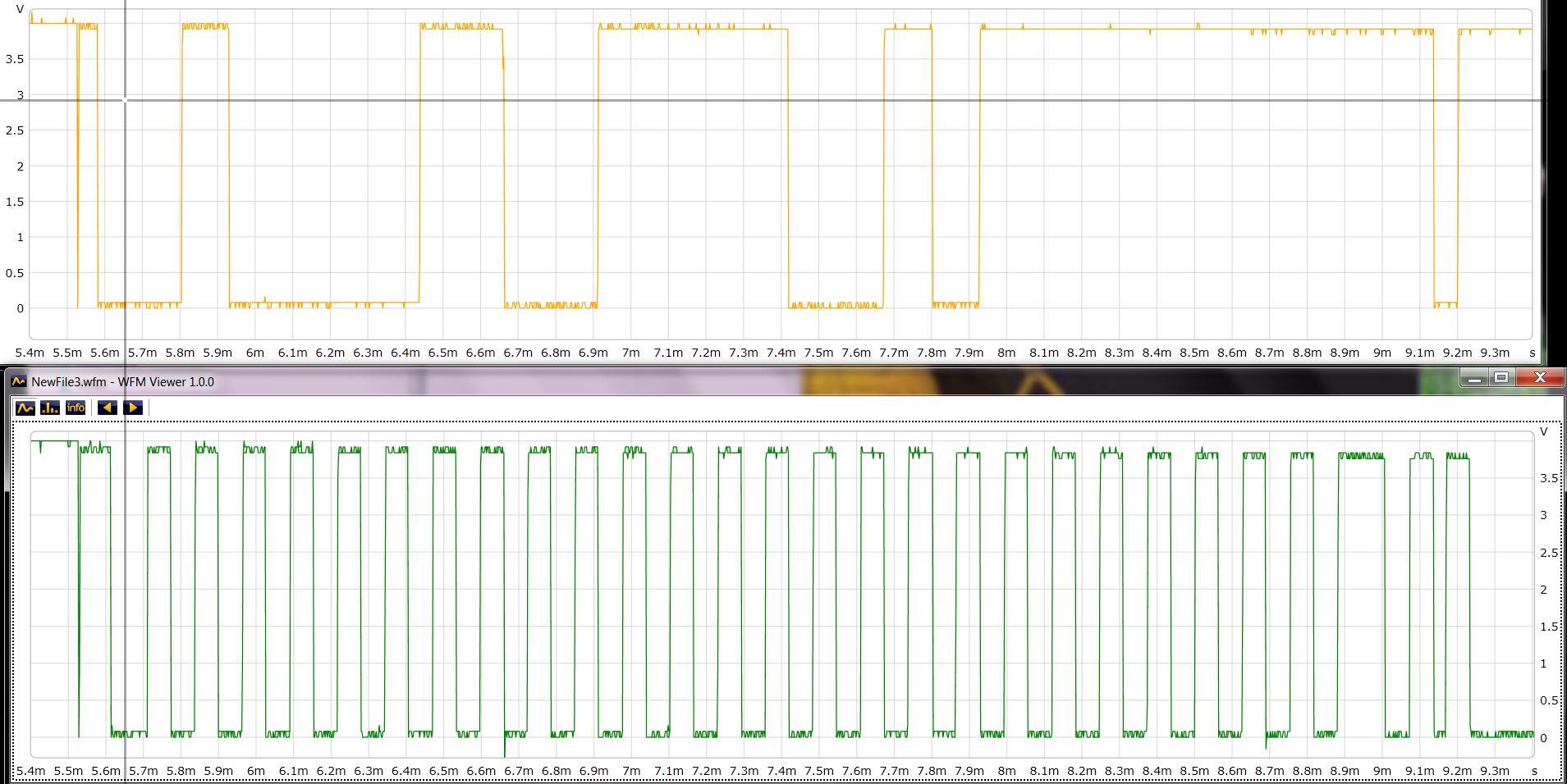