This thread has been locked.

If you have a related question, please click the "Ask a related question" button in the top right corner. The newly created question will be automatically linked to this question.

DS90C387 in Dual Pixel Mode

Other Parts Discussed in Thread: DS90C387

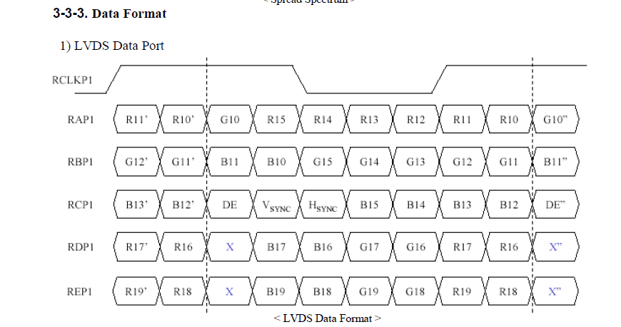
Upon reviewing the LVDS Display Interface (LDI) TFT Data Mapping for Interoperability with FPD-Link app note it states that in order to support both 18-bit and 24-bit inputs you should shift the pixel order. I understand that with 8-bit panels bits 7 and 6 are placed on the 4th LVDS pair. What I don't understand is if you follow the mapping:

RO0 -> R17

RO1 -> R16

RO2 -> R10

RO3 -> R11

...

How does the pixel order gets mapped to the correct LVDS pair? All of the LVDS LCD panel specs I've looked at show LSB as 0 and MSB as 7 and Bits 6 and 7 are mapped to LVDS_O3 and LVDS_E3.

If you look at HDMI/DVI to LVDS Bridge app note it shows 0 -> 0 and 7 ->7. On p3 of that app not he also mentions about the first pixel being odd or even. All the LCD specs I've read state that the first pixel is odd but the mapping in Figure 4 seems correct without having to swap it like the author states.

Hopefully someone can help clarify my confusion.

Thanks,

George

  • Hi George,

    Please note that there are two conventions in LVDS displays for 24-bit RGB color mapping:

    1. MSBs are transmitted on the 4th LVDS channel
    2. LSBs are transmitted on the 4th LVDS channel

    The convention used varies by panel manufacturer.

    Can you take a screen shot of the app note that points to the mapping you see? I see the following:

    This shows the following mapping:

    RO0--> R10

    RO1 --> R11

    RO2 -->R12

    RO3 -->R13

    Mike Wolfe

    DPS APPS / SVA

  • Hi Mike:

    All the specs I have looked at (~10) haveMSBs on the 4th LVDS pair (I use pair because some people call channels odd/even). For 8-bit panels the order is always [X-B17-B16-G17-G16-R17-R16] I may have slipped in my last post and swapped R16/R17 but I've closed a bunch of web pages since then so I'm not sure.

    If we look at the table you've posted and focus on 48-bit it states to take the LSB of your source and connect it to R16 (pin 4) of the DS90C387 transmitter which somehow gets mapped to RO0 of the panel. This is what confuses me. 

    http://www.ti.com/lit/an/slla325a/slla325a.pdf on p4 show 0 connected to 0 (LSB to LSB)

    The DS90C387 talks about Non-DC Balanced Mode which I believe is known as VESA format and is the input expected on just about every panel spec I have read (if it's not the only formataccepted than  VESA format is an optional format accepted). Perhaps the "DC Balanced" Mode referred to in the spec is when you are pairing a transmitter and receiver (to confuse matters more the LDI Demonstration Kit User Manual refers to these modes as OLD (which is VESA) and NEW).

    So given the following:

    • Video source is 8-bit, odd/even, total of 24 (+control) signals
    • 8-bit panel is connected to the DS90C387/A
    • Assume 0 is LSB (for source, 387, and panel) and 7 is MSB
    •  "channel" 0 of the source is the 1st pixel
    • Odd is the 1st pixel of the panel

    Does R0_0 of the source get connected to R10 (pin10) and R0_7 get connected to R17 of the DS90C387?

    According to everything to the eval boards and app notes I've read (except the table you show here from the DS90C387 datasheet R0 should be connected to R0 and the odd channel of the panel should be connected to A0-A3

    Thanks,

    George

  • Hi George,

    When that document was written the VESA spec was old and the Open LDI spec was new. Now both specs are old, and LDI has given way to DVI.

    Let's take a step back to sort out the color mapping. Since different vendors use different naming conventions to describe the color mapping it can all get very confusing. 

    If you refer to Figure 17 in the DS90C387 datasheet you will see the the mapping which converts LVCMOS inputs to the LVDS outputs. The DS90C387 does not process the color data at all. So you can arbitrarily assign colors to any LVCMOS input.  The only bit spaces that are truly unique are the HS, VS and DE spaces. These bit/pin assignments should always get their respective signals.

    So if you take the expected LVDS mapping for your panel and compare it to the datasheet Figure 17, you should be able to determine your pin assignments.

    Can you post a picture or excerpt of the LVDS mapping that your panel uses?

    Mike Wolfe

    DPS APPS / SVA

  • Hi Mike:

    Yes, I totally agree, this all can get confusing, especially if yo don't do it all the time! I follow you on the point that the DS90C387 also doesn't care about colors, it just serializes the bits and places them on the outputs.

    So every LCD panel spec that I have looked at follows this LVDS mapping:

    This happens to be for a 10-bit panel. For 8-bit you don't need the last LVDS (REP1) and for 6-bit you don't need the last 2 LVDS (RDP1 and REP1). I literally just checked 8 different panel specs that I have to confirm this.

    Figure 17 of the DS90C387 makes perfect sense and matches what the panels expect. This makes sense if MSB connects to MSB and LSB connects to LSB but Table 3 in the DS90C387 doesn't seem correct or if you use that mapping then the output won't match what's shown in Figure 17.

    Signed,

    Confused...