This thread has been locked.

If you have a related question, please click the "Ask a related question" button in the top right corner. The newly created question will be automatically linked to this question.

Problems with 8x8 cross point switch SN65LVPC408

Other Parts Discussed in Thread: SN65LVCP408, LMH0394

Hey,

I am trying to switch video inputs using the SN65LVPC408 crosspoint switch and am not able to get a good signal output from the chip.

1. I've connected the SN65LVCP408 chip to one/two cameras and the output to a BCM2835 chip in order to switch between the cameras.

2. When we switch the right inputs to the right outputs, we notice data streaming to the right outputs however the data is very noisy and the total amplitude is ~200mV riding a 2V common mode whereas the input's voltage range is LVDS ~1.5V amplitude.

3. When we switch different inputs to the relevant outputs, we notice a constant 2V common mode.

4. The description of sections 2-3 is also the case when there is no load at the output of the SN65LVCP408.

5. It seems the SN65LVCP408 is receiving a steady 3.3V.

6. We have followed the requirements for resetting the chip (RESN) and keep SWT=0, I2C_EN=1.

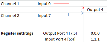
7. We've tried playing a little bit with the I2C registers. We've managed to divert the two input cameras to the output ports and we notice the streaming information change between no data to a low ~200mV noisy data.

8. We've tried playing with the Pre-Emphasis and the Equalization registers. It changes the output but not to the better...

a. Is there any further application notes or an application's schematics example and code?

b. Has anyone encountered this phenomenon and knows how to fix it or what we've done wrong? (non LVDS noisy output voltage at ~200mV pk to pk riding a ~2V common mode)]

Thanks,

Yoav

  • Hi Yoav,

    I have never heard of this situation before from people using the SN65LVCP408. Can you explain more about switching from the right inputs to the right outputs? I am confused over what you mean. The Vocm is higher than what we spec in the data sheet and the Vod is really small, almost like the output is not even switching. Are you holding the RESN pin low all the time or are you simply toggling it after power up?

    Regards,

    Michael Peffers

    High Speed Interface Applications

  • Hey Michael,

    In right inputs I meant the inputs that are connected to the camera and actually have data flowing into them ("wrong" inputs are the inputs without any data).

    I simply toggled RESN after power up (high to low to high). Am I suppose to keep RESN at low?

    Yoav

  • Yoav

    Is the output of your camera LVDS, or is it SDI? - If SDI you will need to convert to a differential signal first with a cable equalizer such as the LMH0394.

    Mark

  • Hi Mark,

    Great point, Thank you for your input!

    Yoav,

    Can you confirm what you input signal to the SN65LVCP408 is for me?

    Regards,

    Michael Peffers

    High Speed Interface Applications

  • Hey,

    Thanks for the direction Mark, it's not SDI but it is also not LVDS, it's SubLVDS.

    Is there any way to work with this protocol with the SN65LVPC408?

    Yoav

  • Hi Yoav,

    I do not see SLVS being a problem for the SN65LVCP408. I ran a test in my lab using the LVCP408 with a Vcm of 900mV and swept the Vid from 50mV to 400mV and the ICs output remained constant.

    Could you please take a scope shot of your input signal and the output of the SN65LVCP408 to post? Also, could you please provide me a basic sketch of what the input and output circuitry look like? What is your measurement technique (i.e. high impedance probe / 50ohms to ground)?

    Regards,

    Michael Peffers

    High Speed Interface Applications

  • Hey all,

    Well, I took my circuit to a better scope and you're probably right about it not being LVDS.

    It seems like both of the signal "polarities" coming out of the camera are the same. This is very weird to me. Does anyone know what protocol this camera is using (it's supposed to use a CSI - sLVDS)?

    Yoav

    Ch1 - Camera Clk out Positive (0A or 3A)

    Ch2 - Camera Clk out Negative (0B or 3B)

    Ch3 - SN65LVPC408 0A out Positive

    Ch4 - SN65LVPC405 Vcc

    Camera_Connected_Without_Series_Capacitance - Camera connected to SN65LVPC inputs 3A,3B, 4A,4B, 5A,5B, output to 0Y,0Z, 1Y,1Z, 2Y,2Z

    Camera_Connected_With_Series_Capacitance_0.01uF - Camera connected to SN65LVPC through series 0.01uF capacitance, inputs 0A,0B, 1A,1B, 2A,2B, output to 0Y,0Z, 1Y,1Z, 2Y,2Z

    Camera_Connected_With_Series_Capacitance_0.01uF_Wrong_Inputs_to_SN65LVPC408_Out - Camera connected to SN65LVPC through series 0.01uF capacitance, inputs 0A,0B, 1A,1B, 2A,2B, output to 0Y,0Z, 1Y,1Z, 2Y,2Z, SN65LVPC408 routed 3A->0Y, 3B->0Z, ...

  • Hi Yoav,

    Are you confident that you have reliable communication with the SN65LVCP408? Are you able to write to the device via the I2C bus and read back the same register with the expected value? Your output should match your input even if your input is not correct. The problem you are having with the output of your camera is outside the scope of this conversation.

    Configuring the SN65LVCP408 can be a little tricky so extra care should be taken to ensure the correct inputs are going to the correct outputs. By default 0A and 0B will be transmitted out 0Y and 0Z. This will probably be the easiest test you can do to ensure that the SN65LVCP408 is working properly. To configure 1Y and 1Z to have 0A and 0B input on them you should write 0x0 to I2C address 0x01. To configure 2Y and 2Z to have 0A and 0B input on the you should write 0x0 to i2C address 0x02 and so on all the way down the list.

    Regards,

    Michael Peffers

    High Speed Interface Applications

  • Hey,

    Yeah, I'm pretty sure I'm communicating with the SN65LVPC408 O.K.

    As I wrote before, It seems the problem is that the camera is not working in sLVDS like I thought it ought to.

    Yoav

  • Hi Michael, 

    I am having the same problems as Yoav has. I have a multi 3G/HD-SDI interface connected to a backplane with 4xdm816x devices (1 mastes, 3 slaves).  

    Also I am using Gstreamer for video processing, so, I use gstreamer pipelines to capture the input and display it in a monitos, also sending 3G/HD-SDI.

    The  3G/HD-SDI input is detected by the slave devices properly, but nothing appears in the output display.

    However, I have tested both switch configurations, SWT (pin #62, Enable switch event when toggled) to high and to low. Nevertheless, nothing appears in the display.

    Which could be the correct configuration to has the output signal?

    Best Regards, 

    Inigo Oyarbide

  • Hi, Inigo,

    I have set up the test in lab. And it works well when switch operation.

    You can set like this according to your design.

    I chose the input port 0 and input port 7 as channel 1 and channel 2. And output port is output 4. The register setting mainly you should set is output port 4 and input port 4.