This thread has been locked.

If you have a related question, please click the "Ask a related question" button in the top right corner. The newly created question will be automatically linked to this question.

Connecting LMH0366 to LMH0302

Other Parts Discussed in Thread: LMH0302, LMH0366, LMH0346, LMH0303

Hi


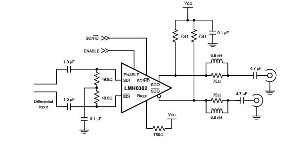
I am busy with a 3G SDI distribution design and want to use the LMH0366 reclocker with the LMH0302 cable driver. Using typical parameters from the respective data sheets:


a. LMH0366 output common mode voltage = 1.2V, differential output voltage = 0.8V.

b. LMH0302 input common mode voltage range for 0.8V differential input = 1.5V to 2.9V.

Based on the above, it seems as if the common mode specification for the two devices are not compatible and will require AC coupling. Is this correct?

Regards

  • Hi Bosr,


    Somebody is looking into this and will respond shortly.

    Regards,

    Michael Peffers

    High Speed Interface Applications

  • Hi Bosr,

    You are correct if we go strictly by the data sheet we need AC coupling.

    This part was supposed to be drop in for a competitor part so we called for the same common mode voltage as the competitor part.The intent is to keep the input voltage, including the swing, between 1.5 and 3.3V. We later tested the device and found out the absolute minimum voltage is 0.9V so we can go below 1.5V. However, if it is possible, with AC coupling we do not need to worry about these. Also, because of pathological video pattern we need to use at least 4.7uF AC coupling Caps.

    Also,  please bear in mind LMH0366 is sensitive to power supply switching noise or adjacent device because of the high VCO gain. Our recommendation is to use LMH0366 with SPI interface so we can increase the loop bandwidth to attenuate the jitter that is being injected into the VCO. We have the following register settings to increase the loop bandwidtth: 

    1. Register 0x19 bits 4:2 should be changed from 000 to 111.
    2. Register 0x0A bit 6 should be changed from 0 to 1.
    3. Register 0x1C bit 6 should be changed from 0 to 1.

    Regards,,nasser

  • Hi Nasser


    Thanks for the reply - this clarify the requirements for connecting the two devices.

    The use of the SPI interface may be a bit of a problem as I will first have to confirm this with the customer. We were looking at a pin-strap implementation of the device and if the SPI interface is required, they will have to implement the software to change register values. We will be using seven of these devices on our board, so VCO sensitivity is a concern. We will also consider reverting back to the LMH0346 although the reduced power consumption of the '66 is attractive.

    One final question on the LMH0366. If the inputs to the device are connected to an AC-coupled source, can I use a simple resistive voltage divider to set the common mode voltage to the middle of the supply rail? Refer TI Application Report SLLA120 fig. 20.


    Regards

    Riaan

  • Hi Riaan,

    LMH0302 inputs are self biased so there is no need for the common mode level shift. Please note below for a recommendation:

    Regards,,nasser 

  • Hi Nasser


    I was referring to the inputs on the LMH0366.


    Regards


    Riaan

  • Hi Riaan,

    Sorry i was still thinking about LMH0302.

    LMH0366 has wide Vcmi dynamic range(0 to Vcc) so i am not sure why you want to level shift to 1.2V. But you can AC couple and level shift as long as you meet impedance requirements.

    Regards,,nasser 

  • Hi Nasser,

    I couldn't find anything in the datasheet that stated that the inputs on the LMH0366 are self-biasing. Being concerned that the common mode voltage would then be undefined I wanted to make provision for an external biasing option. Looking at PCB layout It seems possible to implement this as an option without too much of an impact on impedance.


    Regards

    Riaan

  • Riaan

    Since SMPTE scrambling is not really optimal (there can be large amounts of very low frequency content in the scrambled signal), if possible, you are best off DC coupling the signals.   AC coupling will lead to higher jitter.  We designed the '0366 to have very wide common mode range so that signals could be DC coupled from any source with power supplies which were similar to what the '0366 was running.

    Mark


  • Hi,

    I was planning on using the LMH0303 fed by the LMH0366 but having read several of the posts have major concerns as to the viability of the LMH0366.. Just how sensitive is the LMH0366 not only to power supply noise, but other emission sources.. This seems to indicate that any hope of passing EMI emission and/or susceptibility in "the room of doom" (EMI Chamber) is not looking so good..

    The lower power consumption of the LMH0366 is significant reason for use as compared to LMH0346.. Thus far I have had good results using the LMH0346 on several designs. Please expand on the LMH0366 issues..


    Dave

  • Hi Dave,

    I haven't seen any customer issue related to the EMI(as long as LMH0366 is concerned). However, LMH0366 is sensitive to adjacent VCO or similar frequency. My suggestion is if you are happy with LMH0346 then perhaps it would be a good idea to continue using it. However, power consumption is higher though.

    Regards,,nasser