This thread has been locked.

If you have a related question, please click the "Ask a related question" button in the top right corner. The newly created question will be automatically linked to this question.

Data received by TLK10002 is unstable

Other Parts Discussed in Thread: CDCM7005, TLK10002

Hi,

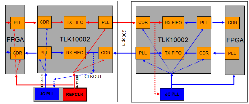
Here is my system setting,

1) TLK10002 works at 4:1 mode, HS speed is 10Gbps, LS side is 2.5Gbps, the reference clock is 250MHz generated by a CDCM7005 PLL

2) LS side is connected to 4 transceivers in an Altera Cyclone IV GX FPGA

3) Both transmission terminals have the same settings. They are connected by a 10Gbps optical fiber link.

After system being booted up,both terminals show lane alignment OK. And LOS signals are low.  Now, i transmit a fixed pattern data from one terminal, let's say terminal A. So called fixed data means at lane 0 a 9'h1BC (K28.5) byte at lest significant byte is always transmitted.  At the other terminal, let's say terminal B, the data received by transceivers in the FPGA  is unstable, which means  1BC is not on lane 0 bit[7:0] or any fixed position unchanged but it jumps randomly in any position among four lanes. I don't know why. Is there anyone who can help me?

I've also checked the F register at terminal B to see the TLK10002 working status. I got the result of "5C2F". It doesn't look good. it says the RX FIFO underflow. What can cause it? 

Looking forward to helps!

  • Hi Yoating,

    Are you using the FPGA alignment code that is required for proper lane alignment for the TLK10002? If yes, what version are you using? v04 is the most recent version and it can be downloaded here.


    Typically when I see an RX FIFO issue it tells me that the quality of the HS link is marginal and needs to be optimized better or their is a clocking issue. Can you confirm that your setting for the HS link is optimal for your use case? Also, I would like to learn more about your clocking architecture. Could you please explain to me how the TX and remote board are receiving their clocks? Would you consider your system synchronous at this point (transmit and receive REFCLK within 200ppm of each other)?

    Regards,

    Michael Peffers

    High Speed Interface Applications

  • Hi Michael,

    Thanks for your email.

    Yes, I am using the alignment code supplied by TI. No where shows the version of the code but from its readme file, the one you call it version v04 is the same as mine in use. Since the alignment signal shows OK i don't think it is the code issue for the lane alignment.

    The remote PCie card and local one are exactly the same design. 

    The clock scheme is this, same crystal oscillators on two cards, which are 25 MHz in frequency, +/- 0.5ppm in stability (Digi-key # CW654CT-ND). This XO goes to a TI PLL, CDCM7005 to generate a reference clock of 250MHz which TLK10002 needs. Based on the data sheets of the PLL and XO i believe the reference clock should be very stable and within the 200ppm range although i have no good ways in which to verify that. It will be appreciated if you can teach me how to do the verification.

    I thought it might be the problem of clocking. Because, if i loop back at HS side locally by a shorting plug in the optical fiber SFP case, it works perfectly. But, no idea how to overcome the fault in remote way. 

    In setting, i use the default values mostly except the followings,

    Reg 1: 0x03F0;

    Reg 2: 0x8117;

    Reg 6: 0xF111;

    After power up the initialization process is followed according to TI instruction on page 64-65 of the datasheet. I have on idea how to optimize the HS link.

    Looking forward to your helps.

    Yaoting

  • Hi Yaoting,


    Sorry for my delay in getting back to you.

    The way to calculate your ppm difference is to measure both respective reference clocks and use this equation:

    A - B / (A / 1e6); where A is typically your dominating clock frequency

    Beside the FIFO errors are you reading any error status (i.e. LOS / HS_DECODE_INVALID) on your remote board? You can read this via the channel status register at address 0x0F Channel_Status_1 where the FIFO errors are reporting.

    To tune the HS link you will simply need to adjust the output drivers transmit pre and post cursor settings via the control registers at 0x05 bits [7:4] and [12:8]. The high speed receiver implements an several tuning features that are located in register 0x04.

    HS_ENTRACK should be set high if you are implementing a link that has little ot no loss. This helps the CDR track th incoming eye better. In high loss situations this should be set low.

    HS_EQPRE: These bits adjust the tap weight setting of the feed forward equalizer (FFE). 1/9 corresponds to the maximum level and 13/9 corresponds to the lowest EQ setting. If you have link up (no LOS condition) a BER test should be performed to test the stability of the link. If the link is marginal which means you receive some bit errors than you should tune the FFE setting in one direction or the other and retest the stability of the link.

    HS_CDRFMULT and HS_CDRTHR: If your eye was moving around slightly these bits allow you to adjust how the CDR tracks any variations in phase. The default value should be sufficient here but you can also try different settings to see which one give you the best BER.

    Unfortunately, there is no easy answer for me to give you to optimize your link. You need to do trial and error until a satisfactory BER level is reach.


    Please let me know how the testing is going?

    Regards,

    Michael Peffers

    High Speed Interface Applications

  • Hi Michael,

    Regarding to your formula of calculating the ppm, I have questions for you as following,

    1) you said in your last post, A is a dominating clock frequency, what does it mean? is it the reference clock, 250MHz, or the crystal osc clock, which is 25 MHz ?

    2) you did not mention the B. To my understanding it should be the same definition on the other side, am i right?

    I've checked 0xF register, the value is 0x5C2F, not 0x5C0F which is expected good status value. So the answer is only the Rx-FIFO has under flow problem. LOS is remaining LOW, which is good.

    We do not have any approaches to get to see the eye diagram of 10Gbps.

    It looks what we only can do is to try those adjustment you mentioned. It is really tough. 

    We are stuck and very anxious under time pressure. Hoping to get more helps from you. If you need my schematic design or anything can help you on the issue i love to do.

    Thanks again.  

  • Hi Michael,

    I don't quite understand the definition of 200 ppm requirement on page 16 of the datasheet. Could you help me?

    If the 200 ppm is defined to line rate, it means the whole clocking system should meet the 200 ppm requirement. That is to say from crystal osc to reference clock which is 250 Mhz should be within that range. The crystal OSC we select is 0.5 ppm at 25 MHz and the CDCM7005 is a jitter cleaner. Can i say it is way better than TKL10002's requirement?

    Strange enough, when i loop back at HS side by a cable, it works well. But when i connect the remote card to local card, it shows either RX-FIFO overflow or underflow.


  • Hi Yaoting,

    The line rate is based off of the reference clock frequency so obviously if your reference clock frequency is +200ppm faster than your line rate will be scaled up by the same percentage. The statement on page 16 of the data sheet is acknowledging the fact that your incoming line rate needs to be within 200ppm of the local reference clock so that the data can be recovered properly. So, if your incoming data is +200ppm and your local oscillator is -50ppm you would be outside the 200pmm spec of the part and the serdes would not recover the data or clock correctly on the remote board.

    In your case this is not the issue. Your local clocks are within 0.5ppm of each other and the HS portion of the remote TLK10002 is operating properly. The problem lies in that the HS and LS portions of the remote chip are not in sync with each other. So data is being put into and taken out of the RX FIFO at different rates which is causing the FIFO collisions.

    The way to fix this problem is to take the CLKOUTxP/N and feed it through the jitter cleaner which in turn will be given back to the TLK10002 as the new reference clock. You will have to use both reference clock inputs on the TLK10002, one for the local oscillator and one for the jitter cleaned version of the recovered clock. In software you will need plan for this switch during configuration. You will initially start with the local oscillator and then switch to the recovered clock some time after. The diagram below should help you understand what I am talking about.

    As far as the equation I provided you with yesterday:

    PPM = A-B/(A/1e6); where A is the dominant clock (ideal clock) and B is the other clock

    EX:

    A = 312.5MHz B = 312MHz

    PPM = 1600

    Regards,

    Michael Peffers

    High Speed Interface Applications

  • Hi Michael,

    The shown above is our board current setting. To my understanding of your instruction, i just need to switch the reference clock on one card either locally or remotely to the output of TLK10002 as a new reference clock after its initialization. Make it become a slave one to sync on the other side which let's call a master. Am I right? Please advise.

    If it is true, what is minimum output frequency out of TLK10002? Could it be 25MHz? I suppose we must us the data stream not from the receiver pll as a source. Right?

    Thanks

  • Hi Michael,

    Good news!

    When i switch the reference clock by using the Output Clock output from TLK10002 at one side after initialization. It becomes stable no underflow or overflow. It looks working now. 

    Thank you very much for your helps.

    Yaoting