This thread has been locked.

If you have a related question, please click the "Ask a related question" button in the top right corner. The newly created question will be automatically linked to this question.

Question of TI RS485 IC

Hi~

Out customer will apply TI RS485 device in RET(Remote Electrical Tilting).

As you know, RET system have many daisy chain.(max 32EA)

If see TI datasheet, it mentioned Unit Load(1/2, 1/4, 1/8) and Up to Nodes per Bus information.

In Case of Unit load=1/2, Up to 64 nodes // In Cae of Unit load=1/4, Up to 128 nodes// In Caseof  Unit load=1/8, Up to 256 nodes

I think that TI RS485 device have fixed Unit Load.

But I can't understand Unit Load definition. Please detail explanation of unit load(1/2, 1/4, 1/8 and so on)

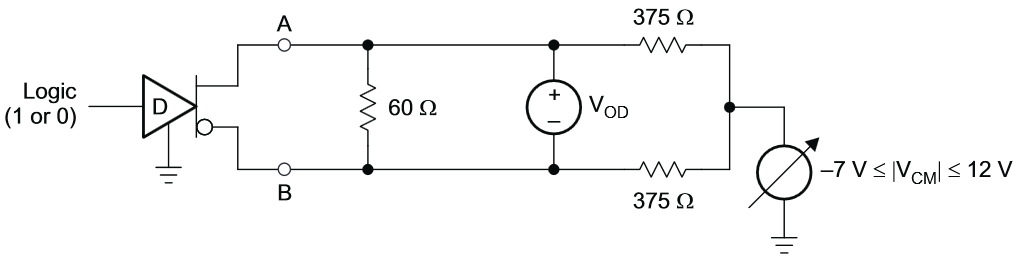
If see Fault conditions of TIA/EIA-485-A Standard(25Page of attached pdf file), It mentioned Idle-line failsafe, Open-line failsafe, Shorted-line failsafe.

What mode should we use in RET system that have 32EA Daisy chain??

For above question issue, Please detail explanation


according to system or function

TSB-89-A.pdf
  • Hi Jayden,

    Please see the wiki note on unit loads below:

    http://e2e.ti.com/support/interface/industrial_interface/w/industrial_interface/2575.the-unit-load-in-rs485.aspx

    In terms of failsafe this will depend on the requirements of your system. Some applications require it and some do not. A lot of new RS485 transceivers have a built in failsafe biasing, which makes it so that when the bus is idle, or shorted together, there is a known output. This is done by creating an offset in the comparator level needed for a logical high output state. Instead of being +200mV and -200mV, you can shift this to -50mV and -200mV (for example).

    But if all of the nodes on the network will not have this feature, and you want to guarantee the output state of each node when the bus is idle, then external idle-line failsafe resistors will be needed. The trade-off is that failsafe resistors add to the overall loading of the bus. I would recommend looking into newer transceivers that have the failsafe state built in. They will cover open, short and idle states and do not add any additional loading onto the bus.

    Please let us know if you have any additional questions.

    Thanks,

    John

  • Hi~ John

    Thank you for your answer.

    Our customer have below question for TI RS485 device.

    1. Definition of Unit Load : 

       - If see related documents, it mentioned as below :

    ""The input impedance of the RS-485 receiver is specified as larger than or equal to 12 kΩ. This impedance is defined as having one unit load (UL). The RS-485 specification specifies the capability to sustain up to 32 ULs.""

    2. Difference point between 1 Unit load and 1/8 Unit load

    3. Measurement Method for difference point between 1 Unit load and 1/8 Unit load

    Our customer need more detail information

    Please detail explanation

  • Hi Jayden,

    1) That definition is generally true.  An RS-485 compliant driver must be able to drive a differential voltage greater than 1.5V when driving an equivalent load of 32UL.  You may have seen the following definition for VOD in the RS-485 specification, and indeed 375ohms is equivalent to 32 1UL receivers (12kohm / 32 ).

    2) A 1/8UL receiver has an input impedance that is 8 times larger than a 1UL receiver.  The input impedance of a 1/8UL receiver is ~96kohm, and the input impedance of a 1UL receiver is ~12kohm.

    3) The Unit Load rating of a receiver is typically specified relative to the input leakage current of its receiver input pins.  That is, a voltage is applied to the receiver input pins A and B ( typically -7V to +12V ), the input current is measured, and the quotient is the input impedance of the receiver.