This thread has been locked.

If you have a related question, please click the "Ask a related question" button in the top right corner. The newly created question will be automatically linked to this question.

Reg: DP83848I Initializing and Link LED Problem.

Other Parts Discussed in Thread: DP83848C, DP83848I

Hi,

    I am using MCB2300 evaluation board along with DP83848 IC. In evaluation board PHY IC initializing perfectly and Link LED also working But same circuit in my board is not working. The difference between Evaluation board and my board is PHY IC Revision, MCB2300 has DP83848C , My board has DP83848I. Is there any difference between those two revisions?

While i am debugging the code in my board PHY IC Device ID is matching but next steps like Auto negotiation and Link status are failing but LINK and ACT LEDs at PC side are blinking. Is there any problem with RJ45 Connector?what could be the problem? Please suggest. I have following observations:

1.PFBOUT voltage is 1.7V

2.MDC is 12Mhz

Thanks & Regards

Parvateesam.

  • Parvateesam,

    As I understand it, you began with an MCB2300 evaluation board, used that as the basis for a new design, and although the evaluation board worked as expected, you are seeing issues with the new design.  Is that correct?

    In terms of configuration and linking, the DP83848C and the DP83848I should function comparably.  We will need to perform some debug of the new design to understand what is happening. 

    It sounds like you have already started down the correct path for debugging this.  Below are some suggestions for additional debug.  Let me know the results of these measurements and we can direct any next steps for debug.

    Patrick


    Power up the board and verify key voltages

    1.Probe the 3.3V supply pins
    2.Probe the PFBOUT and PFBIN pins

    The PFBOUT pin is a regulated 1.8V supply generated inside the device from the 3.3V supply.  The device will not operate correctly if the PFBIN pins do not receive this 1.8V supply.

    3.Probe the RBIAS pin 

    The voltage should be ~1.2V. The RBIAS pin sets the main reference bias for the device.  If the voltage or current for this pin is not correct, it could affect the entire device. 


    Power down the board and verify key resistances

    1.Resistance to ground across the RBIAS resistor should be 4.87 kOhms +/- 1%
    2.Resistance across the transmit and receive terminations should be 50 Ohms +/- 1%
    3.Resistance across the MDIO pull-up resistor should be approximately 1.5 kOhms

    Problems can occur when a very small (10's of Ohms) pull-up resistor is used.


  • Dear Patrick,

    Thank you for your reply. As you said i am facing the issues in my new design which is taken from MCB2300 evaluation board.

    Following are the results of your test points:

    When power up the board:

    1. 3.3V supply is directly feeding to IOVDD33(Pin No.32,48) and AVDD33(Pin No.22)

    2.PWR_DOWN/INT(Pin No.7) is pulled up with 10kohm.

    3.Pin No.20,21,27,39 pins are pulled up with 2.2kohm.

    4.  1.72V is coming from PFBOUT  and it is directly feeding to PFBIN1 ,PFBIN2.

    5. 1.2V is coming from RBIAS pin.


    When powered down the board:

    1. 4.86 kOhms across RBAIS resistor.

    2. 49.9 Ohms across the transmit and receive terminations.

    3. MDIO is pulled up with 10KOhm resistor.


  • Parvateesam,

    Just to clarify, could you confirm that the measurements for the 3.3V supply and the PFBIN voltages were made directly on each pin?  We want to make sure that the voltage is getting into the part and not being hindered by a short or a lack of solder or some other manufacturing issue.

    The pin 39 (RX_DV/MII_MODE) strap will configure the device for RMII mode.  You note that pin 27 (LED_SPEED/AN1) is pulled up.  What about pin 26 (LED_ACT/AN_EN) and pin 28 (LED_LINK/AN0)?  Are these pins pulled up as well?

    Patrick

  • Dear patrick,

         I have verified the measurements for the 3.3V supply and PFBIN directly on each pin.

    Yes ,pin 26 (LED_ACT/AN_EN) and pin 28 (LED_LINK/AN0) pins also pulled up with 2.2K.

  • Parvateesam,

    OK, let's walk through the next sequence of debug steps.

    Patrick


    1.Probe the RESET_N signal

    The reset input is active low and is connected to a 10 kOhm pull down resistor.  It is important to confirm that the controller is  not driving the RESET_N signal low.  Otherwise, the device will be held in reset and will not respond.

    2.Probe the X1 clock

    Verify the frequency and signal integrity.  For link integrity the clock needs to be within +/- 50ppm of the default (25MHz for MII / 50MHz for RMII). 

    3.Probe the TD+/- transmit signals

    Measure the transmit voltages using a 100 Ohm terminated cable.

    4.Probe strap pins during initialization. 

    In some cases, other devices on the board (e.g. MAC) will pull or drive these pins unexpectedly.


  • Parvateesam,

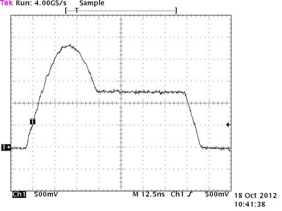
    For reference, I have included below some oscilloscope shots of the expected signaling when probing the transmit signals with the 100 Ohm terminated cable.  When the device is configured for Auto-Negotiation, it will transmit link pulses.  When the device is configured for 100M, it will transmit scrambled idles.

    Patrick


    Link Pulse:

    Scrambled Idles:

  • Hey Patrick,

    i have gone through this thread and will post observations of my board.

    1)PFBout : ~1.72V

    2)Rbias:~1.2V

    3)50Mhz clock seems to be ok. (checked on oscilloscope)

    4)All resistor values seem to be ok.

    5)MDC freq : 1.562Mhz ( what should be the ideal value)

    I have not connected pull up on pin 26.

    Now i am able to communicate dp83848c with my microcontroller.

    But the problem now is when i am connecting it to my computer  , computer does not detect it. I have learned its the most simplest way to setup ethernet.

    I have another Evlautaion kit on which the PC detects that a cable is connected between PC and ethernet magjack on the board.

    I have checked my mag jack connections and they seem to be ok.

    Is there any debug steps to check whether Magjack connections are ok .

    Please help.

    Thanks and regards,

    Mihir Shah

  • Just to clarify, is the information you provided related to the same board and design from the previous posts or a different board?  If a different board, I would prefer to split this post and create a new thread to avoid any confusion. 

    Patrick

  • Patrick,

      I have replaced the PHY chip with new one in my board and now Link LED is glowing when connected to the PC.

    Now i am facing new problem that after auto negotiation process, device is configuring in 10Mbps mode only but when i  ping the device Timing mismatch between the packets error is occurring. But when device is configured in 10Mbps mode directly without using auto negotiation process then it is working properly. Same problem is occurring when it is configured in 100Mbps mode directly   without using auto negotiation process.


    I want to operate the device in 100Mbps mode. I have checked pulses at Tx lines, there link pulses are coming not scrambled pulses when device is configured in 100Mbps mode. 

    please suggest how to configure the device in 100Mbps mode.


    Thanks&Regards,

    parvateesam.

  • Parvateesam,

    The preferred way to configure the operation mode is via Auto-Negotiation.  This process should choose the highest possible speed at which the link can be achieved and choose the right configuration to account for a straight or crossed cable. 

    When configured for Auto-Negotiation, the device will first transmit link pulses to communicate with the partner on the other end of the cable.  Once the device and the partner have exchanged information, it should begin transmitting scrambled idles if both devices are capable of that speed. 

    Based on the straps, I would expect the device to configure for Auto-Negotiation and Auto-MDIX at start up.  Is this the case in your application?  Do you have the ability to read the registers and confirm this? 

    Patrick