This thread has been locked.

If you have a related question, please click the "Ask a related question" button in the top right corner. The newly created question will be automatically linked to this question.

DS92LX2121 Data Lost Occationally

Other Parts Discussed in Thread: LX21EVK01

I am using TI LX21EVK01 for testing the serializer, and I used FPGA to generate pclk, vsync, hsync, and data to the serializer. However, I found there is data lost occationally, and I stuck here.

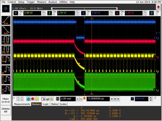
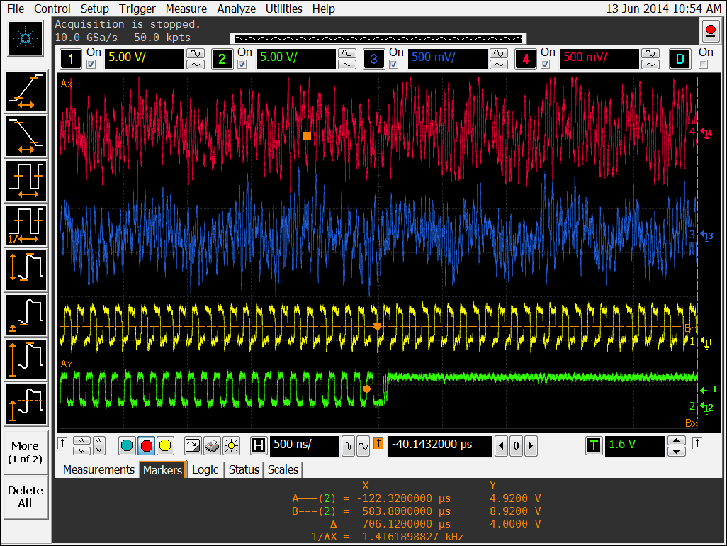
I captured the deserializer's waveforms from my scope, where green color is pclk, yellow is hsync, red is vsync.
It seems tri-state output at this moment, but the pclk input at serializer side is still running.

I would be deeply appreciate if anyone could help me.

Thanks a lot.

Jason LUN

  • Hi Jason,

    The LX21EVK01 comes with the TX and RX boards. The first step to debug this issue is to confirm the RX board is working correctly. Have you tried using the TX board to the RX board, and do you do similar problem?

    Please also provide information about the cable that connect to the RX board.

    An applications engineer will look into this case.

    Regards,

    TK Chin

  • Hi Jason,

    Please trigger your scope using PCLK and then get scope shot and the transmit pair. Then you can attach your cable and monitor the same waveform at the end of the cable.

    Regards,,nasser

  • Hi Chin,

    I am testing with LX21EVK01 TX and RX board with the package USB cable. I am using the default setting as well.
    Basically, I unpack the LX21EVK01, then send PCLK and data to the J1 of TX board, and I got this result.

    Thanks,

    Jason  LUN

  • Hi Nasser,

    I have captured the screen as below:

    From the screenshot,
    Red is Dout+ at deserializer
    Blue is Dout+ at serializer
    Yellow is Pclk input to serializer
    Green is Pclk output from deserializer

    The following screen zoom in the waveform at pclk lost moment:

    Could you suggest any solution for this phenomena? I am using the development kit TX board and RX board with USB cable provided.

    Thanks a lot.

    Jason LUN

  • Hi all,

    I found this error occurs only when the pclk input is higher than 25MHz, however, the datasheet mentioned the pclk input could be 10MHz ~ 50MHz, so I would like to ask whether I need to configure anything before transmitting signal with pclk higher than 25MHz?

    Thanks a lot.

    Jason LUN

  • Hi Jason,

    Device operates, as stated in the data sheet, from 10 to 50MHz. Please note at higher clock rates the setup and hold time becomes more critical. Since there is no error when PCLK is less than 25MHz and  your scope picture show signal quality degradation, perhaps the signal quality is not good enough to enable higher than 25MHz clock rate. I am not sure if you are using a short GND on your scope probe but i see some  noise riding on your signal. Please let us know what type of cable you are using? Do you see higher PCLK rate if you shorten the cable length? Or change to another cable type?

    Regards,,nasser

  • Dear Nasser,

    Thanks for your help, I changed to other USB cable, and it could run up to 48MHz, but it still occur a little error when it run 50MHz. It caused by the USB cable quality, and I could use 48MHz in my application.

    Thanks,
    Jason LUN