This thread has been locked.

If you have a related question, please click the "Ask a related question" button in the top right corner. The newly created question will be automatically linked to this question.

TLK110 not RMII interface not working

Other Parts Discussed in Thread: TLK110

Hi all,

I have asked the same question on Linux forum as well:- http://e2e.ti.com/support/embedded/linux/f/354/p/354901/1246853.aspx#1246853.

I am posting it here, because i see questions about TLK110 more on Ethernet Forum than On Linux. Let me know if it is redundant.


The issue is i am able to access MDIO registers through MDIO bus but RMII interface is not working, using oscilloscope i found out that even TX_EN pin is not high which should be high to enable transmission.

Kindly help.

Thanks and Regards,

Prateek

  • Prateek,

    We can certainly help look at the TLK110 functionality.  I can see some of the pertinent information on the Linux forum.  I have a few questions to help me get up to speed.

    I understand that this is a customer board and uses two Ethernet PHYs - a Micrel KSZ9021 at Phy address 0x04 is connected via RGMII at Eth0 and a TI TLK110 at Phy address 0x01 is connected via RMII. 

    What is the source of the 50MHz RMII reference clock to the PHY?  Can you share your schematic?  

    Patrick

  • Hi Patrick,

    Thanks for quick response. Your understanding is correct about the interfaces.

    TLK110 was originally used for industrial ethernet, but now we are using this as normal ethernet interface. Due to this  we had to change the pin configuration in the hardware as well. Right now changes are done using wires/jumpers; so we don't have a schematic for it.

    50 MHz is provided to PHY and CPSW using an external oscillator (KDS 50.000MHZ).  We have measured as 50Mhz using O-Scope.

    Thanks,

    Prateek

  • If you have some specific questions about schematic, kindly let me know. I'll try to answer them.

  • Hi Patrick,

    Just in case we it is required, below is the list of Software changes which we have done till now.

    • Pin Mux:- 
    static struct pinmux_config rmii2_pin_mux[] = {
        {"gpmc_csn3.rmii2_crs_dv", OMAP_MUX_MODE2 | AM33XX_PIN_INPUT_PULLDOWN}, /* changed the pin mux from
                                                                                   gpmc_wait0.rmii2_crs_dv to this */
        {"gpmc_wpn.rmii2_rxerr", OMAP_MUX_MODE3 | AM33XX_PIN_INPUT_PULLDOWN},
        {"gpmc_a0.rmii2_txen", OMAP_MUX_MODE3 | AM33XX_PIN_OUTPUT},
        {"gpmc_a4.rmii2_txd1", OMAP_MUX_MODE3 | AM33XX_PIN_OUTPUT},
        {"gpmc_a5.rmii2_txd0", OMAP_MUX_MODE3 | AM33XX_PIN_OUTPUT},
        {"gpmc_a10.rmii2_rxd1", OMAP_MUX_MODE3 | AM33XX_PIN_INPUT_PULLDOWN},
        {"gpmc_a11.rmii2_rxd0", OMAP_MUX_MODE3 | AM33XX_PIN_INPUT_PULLDOWN},
        {"mii1_col.rmii2_refclk", OMAP_MUX_MODE1 | AM33XX_PIN_INPUT_PULLDOWN},
        {"mdio_data.mdio_data", OMAP_MUX_MODE0 | AM33XX_PIN_INPUT_PULLUP},
        {"mdio_clk.mdio_clk", OMAP_MUX_MODE0 | AM33XX_PIN_OUTPUT_PULLUP},
        {NULL, 0},
    };
    
    • Changed device file and board file for supporting second Ethernet interface with correct phy address. (arch/arm/mach-omap2/*)
    • To support Software strapping, we have pulled down the pin 21 (SW_STRAP) and in generic driver (inside function genphy_config_init) writing to SWSCR1 (Address 0x0009 & Value: 0xfc01).
    • I have also tried restarting auto-negotiation but in that case it never initiates the auto-negotiation at all (setting and waiting for BMCR bit 9 to get reset).
    • Have selected RMII mode using pin MII_MODE (RX_DV) by pull up of 2,2K for it. and also seeing this change getting reflected in register dump. (on Reading Extended register: RCSR: 0x0017, value is:- 0x0017:- 0x0021 ).

    Please let me know if there are any mistakes in list above.

    Thanks and Regards,

    Prateek

  • Hi Patrick,

    Attached file is schematic which we just created to show the wiring/jumpers which we use to do the connections for TLK110 (RMII Interface). 8424.BWIR_RMII.pdf

    Kindly let us know your review comments on it.

    Note: Processor pin numbers are shown in off page connector.

    Thanks and Regards,

    Prateek

  • Hi Patrick,

    We are still stuck with this issue. Unable to proceed. Did you get a chance to have a look at schematic or list of changes i had posted in this thread? Kindly let us know if there is anything we can try to resolve this issue.


    Thanks & Regards,

    Prateek

  • Prateek,

    I have a few comments on the schematic:

    1. The RBIAS resistor is shown as 4.7 kOhms.  This resistor must be 4.87 kOhms +/- 1%. 
    2. The device side center taps on the transformer should be biased to 3.3V.  In the schematic, they appear to be capacitively coupled to DGND. 

    You mention that TX_EN is not high.  TX_EN is an input to the PHY.  We need to understand why this signal is not asserted by the MAC.

    For the purposes of debug, I would suggest that we simplify the setup as much as possible until we get basic functionality working.  To that end, I would question if software strapping is necessary.  Could we disable this for now and skip this step?

    Patrick

  • Hi Patrick,

    Thanks for your comments on schematic.

    Yes, software strapping can be disabled for now. We'll do the necessary changes in software and hardware both for it and post the results here. In Hardware we will just pull the pin high and in software, i'll stop writing to the Bit 15 in SWSCR1 register. Is that sufficient?

    Thanks and Regards,

    Prateek

  • Prateek,

    I believe this will be sufficient.

    Patrick

  • Hi Patrick,

    We followed last post. Disabled the software strap (In HW and SW) and have done both the changes in the schematic. Ethernet interface still doesn't work. Do you have any suggestion to debug this further and check something else in HW and SW while these changes are in place?

    Regards,

    Prateek

  • Prateek,

    I have shared this with my colleagues and I am waiting for their feedback and suggestions.  It may be Monday before I have that. 

    In the meantime, perhaps we can further confirm the functionality of the PHY.  I would like to suggest that we confirm that the device under test will link to itself.  This can be accomplished using a loopback plug.  Below is some information on how to create the necessary cabling:

      1. Cut a cable with about 1 foot of cable and the RJ45 connector
      2. Strip off about 3~4 inches of the outside plastic shield to expose the 4 pairs of twisted pair cable
      3. Bend back pairs 4/5 and 7/8 (these will not be used)
      4. Solder pair 1/2 to pair 3/6
            1. Solder wire 1 to wire 3
            2. Solder wire 2 to wire 6
      5. Now you have a loopback cable.
    Plug the cable into any operating 10/100 Ethernet port and link will be established (assuming Auto-Neg is enabled).  You can also force 100BASE-T or 10BASE-T full duplex to test those modes explicitly.

    With the loopback cable in place, you should see the link LED light.  I would like you to dump out the complete register set for addresses 0x00 - 0x1F with the loopback plug in place.  Please read each register twice as some registers latch their previous status such that getting the current status requires a second read. 

    Patrick

  • Hi Patrick,

    I have made Ethernet Loopback cable as mentioned by you. I tested it with PC and confirmed that it works (LEDs blink).

    But when i connect it to the ethernet port eth1 which is connected to TLK110, it doesn't work, output of ethtool suggests that Link has not been detected. See the ethtool output below.

    Settings for eth1:
            Supported ports: [ TP MII ]
            Supported link modes:
            Supports auto-negotiation: No
            Advertised link modes:  Not reported
            Advertised pause frame use: No
            Advertised auto-negotiation: No
            Speed: 10Mb/s
            Duplex: Half
            Port: MII
            PHYAD: 1
            Transceiver: external
            Auto-negotiation: on
            Current message level: 0x00000000 (0)
    
            Link detected: no

    And Register Dump is as below.

    ___________________________Register Dump_________________________________
     Address	                 Value
    0x0000			0x3100
    0x0000			0x3100
    0x0001			0x7849
    0x0002			0x2000
    0x0004			0x01e1
    0x0005			0x0000
    0x0006			0x0004
    0x0007			0x2001
    0x0008			0x0000
    0x0009			0x7c01
    0x000A			0x0105
    0x000B			0x0000
    0x0010			0x4002
    0x0011			0x0108
    0x0011			0x0108
    0x0012			0x0000
    0x0013			0x0000
    0x0014			0x0000
    0x0015			0x0000
    0x0016			0x0100
    0x0017			0x0021
    0x0018			0x0400
    0x0019			0x8021
    0x001A			0x0000
    0x001B			0x007d
    0x001C			0x05ee
    0x001E			0x0102
    0x001F                    0x0000

    I have also tried the same Loopback cable in the interface eth0 (Phy KSZ9021) which works usually with normal ethernet cable but it shows the same  behavior (not working) in case of loopback cable.

    Let me know what you infer from the register dump. One thing which i notice is that auto-negotiation doesn't get complete.

  • Hi Prateek,

    Sorry for joining late on this. Can you please the following items:
    1. Can you measure the CLKOUT pin with scope?
    2. Can you measure NLP on the TD_P/N or RD_P/N pins with scope?
    3. Can you force 100BT (Reg 0x0, bit 12) and measure the MLT3 signal on the TD_P/N or RD_P/N pins with scope?
    4. I saw on register 0xA, bit 0, you set it to one. According to your schematic, you don't use RX_CLK, so you need to set this bit to zero.

    Thanks,
    Noam

  • Hi Noam,

    Noam Sadan said:
    1. Can you measure the CLKOUT pin with scope?

    Yes, CLKOUT is 50 MHz.

    Noam Sadan said:
    2. Can you measure NLP on the TD_P/N or RD_P/N pins with scope?

    There is no activity on these lines.

    Noam Sadan said:
    3. Can you force 100BT (Reg 0x0, bit 12) and measure the MLT3 signal on the TD_P/N or RD_P/N pins with scope?

    There is no activity on these lines in force mode as well.

    Noam Sadan said:
    4. I saw on register 0xA, bit 0, you set it to one. According to your schematic, you don't use RX_CLK, so you need to set this bit to zero.

    Register contains valid information or have effect on the operation only if SW strap is enabled (I think as per Datasheet). So does it matter what value of this register holds if SW strap is disabled (SW strap is disabled in our case). However, I have reset that bit to 0 now, still same operation.

    Regards,

    Prateek

  • Thanks Prateek.
    Please also measure the voltage seen on the following pins:
    1. PWDN pin (#7) when the TLK110 is working
    2. SW_Strap pin (#21) when the TLK110 is in reset

    Thanks,
    Noam

  • The value at PWDN:- 3.28V and SW_strap: 3.29V.

  • Thanks Prateek.

    I would like to continue with the following:
    1. Can you try and RESET the TLK and check again?
    2. Can you please send register dump just after the reset completes?
    3. Can you measure current consumption of the 3.3V supply of the TLK?

    Thanks,
    Noam

  • Hi Noam,

    Noam Sadan said:
    1. Can you try and RESET the TLK and check again?

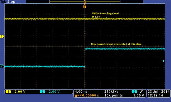
    While reset the pins are at 3.3V. Please find the attached o-scope snapshot for PWDN pin while reset.

    Noam Sadan said:
    2. Can you please send register dump just after the reset completes?

    I am a little confused on how to perform this. Do you want me to do a software reset for PHY and once reset is complete, dump the register and send you the log?

    Noam Sadan said:
    3. Can you measure current consumption of the 3.3V supply of the TLK?

    Since our design doesn't have an option to check the current. I don't find any option at all to measure the current consumption.

    Also what do you think is going on looking at previous posts in this thread. If you can point out some problem, then i would be glad to have a look at it in parallel. We are stuck with this issue. 

  • Prateek,

    Thanks for the info. I understand this is urgent and will do my best to help you solve this.
    It looks like the TLK is in SW Strap mode or PWDN mode, as for my understanding you have register read/write abilities but don't see any activity on the TD/RD lines. The confusing part is that your current measurements are indicating the TLK is not in PWDN mode and SW Strap pin was connected to PU (R226), so should be disabled.
    Another register dump would help - it would be great if you can read them just after you release the reset, so we would know what strapping are enabled. 
    Just for better understanding the TLK status, can you please measure the voltage developed on the RBIAS (R227)?

    Thanks,
    Noam

  • Hi Noam,

    Thanks for understanding the situation. Yes, we have register read/write access but no activity on TD/RD lines. 

    The voltage on RBIAS (R227) is 1.23V. 

    Noam Sadan said:
    Another register dump would help - it would be great if you can read them just after you release the reset, so we would know what strapping are enabled. 

    I'll need some time before i can figure out how to perform this task, because when reset is done, it happens for whole board and linux reboots, i'll have to wait for around 7-8 seconds before MDIO driver is loaded and i get a register dump. Do you have any other alternative for this or wait for 7-8 seconds is ok or do you want me to do a software reset and read the register?

  • Hi Prateek,

    On the register reading, you can only disable any registers writings by the MAC after reset and than read the registers. Waiting for the 708 seconds is OK.

    Thanks,
    Noam

  • Hi Prateek,

    Have you managed to get the register readings?
    Can you also verify the MAC is not holding any of the Tx signals?

    Thanks,
    Noam 

  • Hi Noam,

    Sorry for so delayed reply, i was caught up with something else. Here is the register dump.

    Val[0x0000]:-0x3100
    Val[0x0001]:-0x7849
    Val[0x0002]:-0x2000
    Val[0x0003]:-0xa211
    Val[0x0004]:-0x01e1
    Val[0x0005]:-0x0000
    Val[0x0006]:-0x0004
    Val[0x0007]:-0x2605
    Val[0x0008]:-0x0000
    Val[0x0009]:-0x7c01
    Val[0x000A]:-0x0104
    Val[0x000B]:-0x0000

    Val[E0x0010]:-0x4002
    Val[E0x0011]:-0x0108
    Val[E0x0012]:-0x0000
    Val[E0x0013]:-0x0800
    Val[E0x0014]:-0x0000
    Val[E0x0015]:-0x0000
    Val[E0x0010]:-0x4002
    Val[E0x0011]:-0x0108
    Val[E0x0012]:-0x0000
    Val[E0x0013]:-0x0000
    Val[E0x0014]:-0x0000
    Val[E0x0015]:-0x0000

    Kindly let me know if you can infer something significant out of this.

    Thanks & Regards,

    Prateek

  • Hi Prateek,

    Can you please try to write register 0x9, bit 0x15 to 1?
    This should write "Config Done" to SW_Strap mode.
    If this doesn't help (or you already tried it and I missed that), can you please address the following:
    1. How many boards have you tried?
    2. if you tried only one board, can you try a second board?
    3. Can you try to replace the TLK110 with another TLK110 and re-check?

    Thanks,
    Noam

  • Hi Noam,

    Thanks for your reply.

    Noam Sadan said:
    Can you please try to write register 0x9, bit 0x15 to 1?

    I have tried this but this didn't change anything. It still doesn't work.

    Noam Sadan said:
    1. How many boards have you tried?

    We have tried two different boards in which TLK110 had RMII interface and one board in which it had MII Interface. Right now i am working in MII Interface mode.

    Noam Sadan said:
    2. if you tried only one board, can you try a second board?

    Have done it. Would you still want me to use another board in MII Interface.

    Noam Sadan said:
    3. Can you try to replace the TLK110 with another TLK110 and re-check?

    It is possible, but wouldn't changing the board mean changing the TLK110 itself? I will try changing the IC and let you know the results.

    Is there anything in your mind which i can try in the software? 

    Note: I am doing these changes in the u-boot right now since you wanted a register dump from PHY when there is nothing written in PHY Register by CPSW.

  • Hi Noam,

    I have an update on this one. I wanted to confirm that the TLK110 MAC and ethernet connector side is working, so for this i tried the loop-back feature provided in TLk110 using BIST on Industiral Development Kit ..and my custom board.

    I have tried following tests:

    • PCS input Loop-back (near end)
    • PCS output Loop-back (near end)
    • Digital Loop-back (near end)
    • Far-End Loop-back test

    These tests pass on IDK but fail in my custom board. I confirm it by reading BIT-7 in BISCR reg: 0x0016 for near end loop-back no receive event occurs in PHY, while and for far end tests i saw the packets coming back through the loop-back on PC running WireShark.

    Do you have any comments on it? 

    Thanks and Regards,

    Prateek