This thread has been locked.

If you have a related question, please click the "Ask a related question" button in the top right corner. The newly created question will be automatically linked to this question.

Repeaters in cascade (ISO15)

Other Parts Discussed in Thread: ISO15

Hi,

I'm looking for communication that can handle a network with ~250kbps for one 10km segment (very large scale network).

In your website, I found the ISO15 Isolated 3.3V, Half Duplex, RS485 Transceiver that combined with Dual isolated half-duplex repeater (figure 5*) (and Design for dual isolated power supplies (figure 6*)), might be suitable for my application.

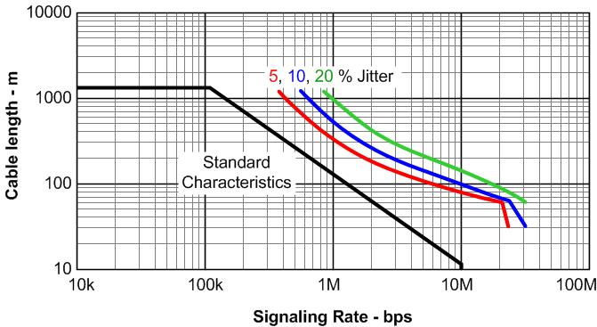
My question is how many repeaters can I connect in serial/ cascade? (The number should be every ~700 meters (somewhere around 14 repeaters for 10km) (Figure 1*)?

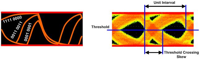
Another question would be about the jitter. Is it correct to assume that if I'm working with 250kbps, I will get 5% jitter (according to Figure 1)? Is using the repeaters in cascade will make it worse? Is it o.k if the system will have 5% jitter for the entire bus?  

*"Data-rate independent half-duplex repeater design for RS-485", Applications Engineer (attached herewith)

Thanks a lot,

Idan\

2251.8304.Data-rate independent half-duplex repeater (TI).pdf

  • Hello Idan,

    yes it is possible to cascade multiple bus segments (in your case up to 14) in series to reach 10 km. In fact there is one Chinese coal mine where this principle is applied by connecting 20 segments of 1 mile length (~1.5km) in series for a maximum bus length of 20 miles. In the mine application however, the data rate is limited to 20 kbps for the reason you also mentioned above: minimized jitter.

    5% jitter for the entire bus is acceptable. However, 5% jitter for a single segment will add up to a significant jitter number for the entire bus.

    As RS-485 is typically used for master-slave networks,  system designers apply various strategies to finding a compromise between maximum data rate versus maximum reliability.

    On the one hand you might keep the logic state of a bit stable for the duration of the entire bus propagation delay. This will drastically reduce your data rate but maximize reliability and reduce overall jitter because you won't change any bit status until even the last transceiver in the network has received this bit.

    On the other hand you could maximize the data rate by keeping the bit stable for the prop-delay of a single segment only, simply because after the first repeater (or buffer) this bit has been restored. Then of course each segments' contribution to the overall jitter becomes notable.

    In coal mines RS-485 networks are used for the detection and alarming of hazardous and explosive gases. So reliability is of highest priority. Hence a slow data rate of ~ 20 kbps is preferred.

    Thank you for referring to my article on the dual-isolated half-duplex repeater.

    Best regards, Thomas Kugelstadt

  • Hi,

    First, thank you for your quick response!

    In the "Chinese coal mine" application, you mentioned that they worked with 20kbps for the 20 miles length. My question is why that low? According to Figure 1*, at about 100kbps there is no jitter at all so it doesn't piling up. Is there any way to calculate the jitter along the distance and the numbers of repeaters or the final baud rate should be determine at the final "eye pattern" and BER check?  What cases the jitter to appear? Do you have any application note/ white paper about that?     

    *"Data-rate independent half-duplex repeater design for RS-485", Applications Engineer.

    Thanks a lot,

    Idan

    6558.Data-rate independent half-duplex repeater (TI).pdf

  • Hello Idan,

    Why the low data rate of 20kbps?

    Because some network designers try saving dc-power consumption by avoiding termination resistors at the bus ends. This of course will cause line reflections, which at high data rates of 200kbps, destroys entire bits and leads to data errors. However, when reducing the data rate, or lengthening the bit time, these reflections are allowed to occur during the first say 10% of the bit time, After that time the signal settles to a steady state for the remaining 90% of the bit time.

    I do not encourage this type of system design but recommend instead proper line termination for maximum signal integrity and minimum data errors.

    What causes Jitter?

    Signal jitter is primarily due to inter-symbol interference (ISI), which in turn is the net effect of several causes of signal degradation. One cause is the attenuation and the dispersal of frequency components that result from signal propagation. Another cause is "pattern-dependent skew", which is the variation of rise and fall times that follow the varying sequences of ones and zeros of pseudo-randomly generated binary patterns (PRBS). A data pulse responds to these effects with a loss of amplitude, displacement in time, rounded edges, and a "smearing" of the pulse into adjacent unit intervals.

    Figure 1a shows the ISI, or pattern-dependent time skew for three different bit patterns. Here a series of ones followed by a zero charges the cable capacitance to the highest line voltage possible. This combination of bits will therefore produce the longest fall time to reach the zero crossing point. In contrast to that, for a string of zeros followed by a one and then a zero, the one-to-zero transition starts falling from a voltage much closer to the zero crossing, thus taking less time to reach the zero crossing.

    Figure 1. a) Pattern-dependent skew and b) eye-pattern diagram

    Measuring the signal transitions over a wide range of PRBS data yields an eye-pattern such as the one in Figure 1b. An eye-pattern allows a visual assessment of the quality of a transmission link. The less ISI the smaller the jitter, or eye-closure, and the wider the eye opening. Eye-closure or jitter is expressed in percent and is defined by the ratio of the threshold crossing skew to the unit interval:   Jitter (%) = threshold crossing skew / unit interval.

    Segment Length and Data Rate

                 Figure 2. Cable-Length vs signaling Rate characteristic

    Following the standard characteristic you might be able to drive 700m at 200kbps and 500m at 250kbps without jitter. Note that even a 1% jitter accumulates and can cause difficulties at the end of 14 or 20 segments.

    in the case of a 500m line with a signal velocity of 5ns/m, the propagation delay through the line will be 2.5us. Adding the total prop-delay of a repeater (one receiver + one driver) of 440ns, yields a total prop-delay for a single segment of 2.94us ~3us. At 250kbps the shortest bit time (or unit interval) is 4us. So a single bit will be stable until it has reached the end of a segment (which is good but not necessary).

    Multiply the segment prop-delay by the number of segments i.e. 3us x 20 = 60us. This is the total prop-delay for the entire distance of 10km. So if a master node sends a sequence of data to a 10km distant slave node receiver, the master node will have to wait for at least 2 x 60 us before it can expect receiving the first response bit from the remote slave node.

    With regards to the signal fidelity check, you are absolutely correct to perform an eye-pattern and BER check to confirm your mathematics proofs correct.

    Best regards, Thomas