![]() Cool RS-485: Receiver Equalization Boosts Bus length of High-speed Networks
Cool RS-485: Receiver Equalization Boosts Bus length of High-speed Networks
High-speed RS-485 networks in motion encoder and traffic monitoring systems are pushing for bus lengths beyond 100 m. This however requires the compensation of frequency dependent cable losses, predominantly existing at high frequencies. The two, most commonly applied and inexpensive compensation techniques are driver pre-emphasis and receiver equalization.
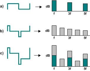
Figure 1. a) Principle of cable loss compensation via b) pre-emphasis, and c) receiver equalization
Driver Pre-emphasis
Pre-emphasis increases the high-frequency content of the original signal prior to entering the transmission medium (Figure 1b), by briefly boosting the driver output to almost twice the amplitude of the original signal. Figure 2 clarifies the theory behind it.
Figure 2. Harmonics spectra of a 50 % duty cycle (a), a 25 % duty cycle (b), and the combined signal (c)
While the output signal of a conventional driver with 50% duty cycle purely consists of odd harmonics of the original square wave (Figure 2a), a 10% duty cycle pulse presents off and even harmonics in its spectrum (Figure 2b). The combination of both wave forms then yields a spectrum enriched in high-frequency content and with higher signal levels (Figure 2c). Thus, boosting the driver output briefly generates the necessary upper harmonics that counteract the low-pass response of the transmission cable. It also creates sharper signal edges at the receiver input with less displacement in time keeping inter-symbol interference (ISI) at a minimum.
Unfortunately pre-emphasis has serious drawbacks such as:
1) The violation of the EIA-485 standard by exceeding the specified maximum of 10% signal overshoot by some cool 90%,
2) The inapplicability in electromagnetic interference (EMI) sensitive applications due to the high-frequency emissions caused by the pre-emphasis pulse,
3) An approximate four times higher instantaneous power consumption due to the high pulse amplitude and the associated current boost.
Receiver Equalization
The less spectacular receiver equalization contents itself with the amplification of the high-frequency components of the receiver input signal. Here, an active high-pass filter is implemented between the cable end and the input comparator. While this approach is straight forward, noise-sensitivity considerations make the optimization of the internal filter response to certain applications necessary. Thus lower filter orders are applied for approximating the cable attenuation in the lower megahertz-range, while higher filter orders provide equal accuracies in the tens of megahertz.
Receiver equalization reigns over pre-emphasis by:
1) complying to the EIA-485 specifications for maximum driver voltage overshoots,
2) avoiding high-frequency emissions, thus making it the preferred solution in EMI sensitive applications,
3) and keeping the increase in power consumption due to the added filter circuit negligible.
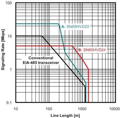
Figure 3 compares the signaling-rate-versus-line-length characteristics of two transceivers with receiver equalization with the characteristic of a conventional EIA-485 transceiver.
Figure 3. Data rate vs line length characteristics in comparison
The diagram above shows that for 200 m cable length the data rate of device A can be 10-times the data rate of a conventional transceiver. At 1000 meters the data rate of device B maxes out at 5-times that of a transceiver without equalization. In the extreme case of a 1500 m cable device B is still capable of transmitting at 1 MHz.
Conclusion
Receiver equalization is the preferred technique to extend the usable limits of EIA-485 data communications, while complying with the EIA standard. Increasing the signaling rates, or cable distances over inexpensive cables are easily achieved.
Feel free to evaluate our SN65HVD23 and SN65HVD24 transceivers with integrated receiver equalization and proven performance advantages.


