This thread has been locked.

If you have a related question, please click the "Ask a related question" button in the top right corner. The newly created question will be automatically linked to this question.

DP83848C - Several just died..

Other Parts Discussed in Thread: DP83848C, LM5116

Hi,

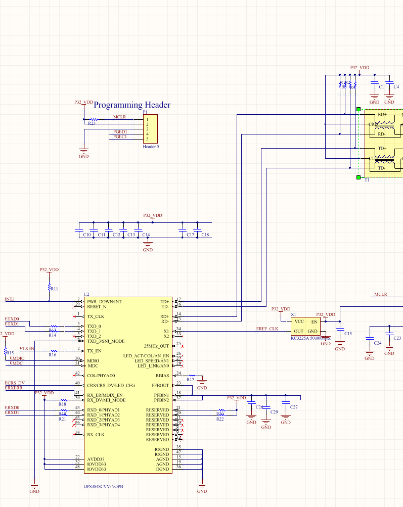
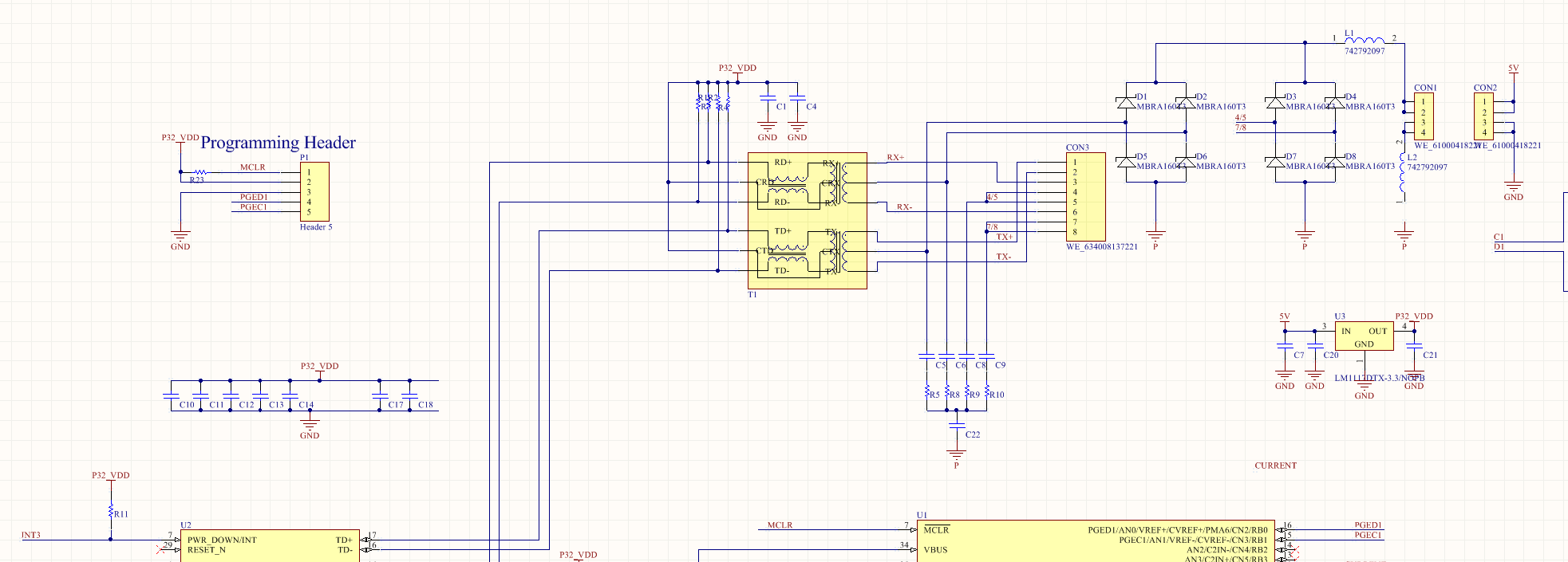
I'm working on a new product concept, and I've got a DP83838 in RMII mode attached to a Microchip PIC32.. I've had hit and miss results and some units have worked fine, and others don't.   When i scope them out,  I find the TX_CLK pin is always dead as well.. I good ones the TX_CLK pin is active..

Replacing the DP83838 has cured it, and then later on its died again.  

Is it possible that my choice of Ethernet Transformer is a problem?  I'm using a Wurth 749012011 .    

I've just run up 2 more prototype boards, it is a possibility i had something faulty..

Any clues?   

  • Andrew,

    I am not sure what is happening here, but I can certainly confirm that what you are seeing is not expected.  More debug will be required to figure out what is happening.

    In terms of probing, I would be interested to know what voltages you see on the supply pins, the RBIAS pin, the PFBOUT pin, and the PFBIN1 / PFBIN2 pins.  Do these voltages change for a functional board and a non-functional board?

    What other differences can you identify between a functional board and a non-functional board?  Are you able to read registers?  Do you see any signaling on the cable pins of the PHY?  Is there any signaling on the 25MHz_OUT pin?

    Patrick

  •  I built up another Prototype board from stractch and i'm not getting the same problems..   I'm guessing perhaps i had a problem with the board somewhere else.

  • Andrew,

    Glad to hear that you are now having success.  Would it be acceptable to close this post?

    Also, for the sake of clarity, I plan to change the title of the post to reflect the device shown in your schematic, the DP83848C.

    Patrick

  • It ran for 3 days, pretty much continuously, and then died.  Replaced the PHY chip and it was all good again. 

    Two things i've noted. When the PHY fails, the current draw on my board increases by about 200mA.   The PHY gets quite hot, after it fails.  This time, when it failed, it dragged the clock input down as well.    ( i did't notice that last time )

  • Rbias Voltage = 1.28V

    PFBOUT = 1.96V +/- 0.04V

    PFBIIN 1 = 1.96 +/- 0.06V

    PFBIN2 = 1.98 +/- 0.04V

    I'm getting a 50Mhz clock on Pin 1 ( TX_CLK ), and Pin 25..  ( I'm using 50Mhz, as its RMMI )

    its running now, i'll measure it, if i get a failure again.

  • These measurements are on a functioning device, correct?  They are all on the high side.  Nominally, the Rbias voltage would be 1.2V and the PFB voltages would be 1.8V. 

    Could you power down the device and measure the resistance of the Rbias resistor?  This resistor sets the main current bias of the device.  If this resistor were too small, e.g. 487 Ohms or 48.7 Ohms instead of 4.87 kOhms, the device would draw more current than is intended.

    Patrick

  • (1) Rbias = 4.85kohms, as measured in the circuit.

    (2) My Cpfb i'm using its a 10uF Ceramic.  I saw in the data sheet that it was suggested to use a tantalum? Is that join to be a big issue?

    (3) I've gone and re-measured a bunch of points around the IC.    This one has been running pretty much fine. 

    Pin     Description   DC Value 

    15     AGND            3mV,  ( with respect to ground )

    18     PFBIN1         1.71V

    19     AGND            1mV

    22     AVDD33        3.31V

    23     PFBout          1.70V 

    24     RBIAS            1.15V

    29     RESET_N     3.31 Volts

    35     IOGND          ~25mV 

    36     DGND           ~25mV

    37     PFBIN2         1.70 Volts

    47     IOGND          ~30mV

    48     IOVDD33     3.3Volts

    (4) would the selection of Transformer be playing into this?    Im using this one..
    http://katalog.we-online.de/pbs/datasheet/749012011.pdf

    (5) I'm pulling power from the ethernet, as well ( PoE ), that seems to be working fine.. 

    Given this is an intermittent problem its really hard to determine what might be the problem!

    I can send you the schematics, but rather not post it publicly.

  • Ok got a "controlled" Failure, and i'm now sure that the problem only occurs on turn on or plug in.. I think this is due to Transienets that are sneaking across my Transformer  ( Its a POE circuit  )..

    After failure, the PHY draws a lot of current. 

    Can you suggest any way of protecting against the transients?

  • Hi Andrew,

    What PoE type of alternative are you using (is it A)? For the PHY that fails, is it on the PD or PSE side? Are you using a transformer that is PoE compatible?

    Regards,

    Ross

  • See the schematic of the POE Setup..     The transformer is defiantly POE compatible.     The Phy that is dying is the PD side.        DC from the Cable is pushed to a separate DC/DC module via the headers that are on the right hand side.        

    Fault only occurs on plug in/unplug.   I'm trying to capture it on the scope but its not that easy!

  • Thank you for the clarification. What chip set is the PD controller? Do you have any ESD termination paths on the PD side? From the schematic all I see is a Bob Smith termination and a diode bridge. 

    Regards,

    Ross

  • The PD controller is a NP1093.    (http://www.onsemi.com/pub_link/Collateral/NCP1093-D.PDF)    This is on a separate board, which also contains the DC/DC converter.   ( LM5116 converting the  Poe DC to 5V  ).

    There is D2 across the input power supply, on the second board..  ITs a 1SAM58AT3G, and its there for ESD protection.. I'm not seeing any ESD issues on this side of the transformer.

    I'm sure the issue is on the PHY side of the transformer.

  • Not sure if its possible, but can i open a support call with TI on this?   

  • Thank you for the schematic and IC used. I will look over the datasheet get back to you. I will check with my coworkers about extra ESD protection. You do have a long path before ESD can be terminated (diode bridge, inductor and headers to another board). 

    Regards,

    Ross

  • Hi Andrew,

    It seems like this is a PoE issue like you stated earlier. There are a lot of application notes on proper methods for implementing PoE devices to protect PHYs and other components. For instance, here is a link to an app note on ESD for PoE. (http://www.ti.com/lit/an/slva233a/slva233a.pdf)

    This might help you narrow down the source of the issue and also give you ideas to mitigate the transients.

    TI does offer a large portfolio of PoE devices and reference designs that might aid you as well.

    http://www.ti.com/lsds/ti/power-management/power-over-ethernet-products.page

    Regards,

    Ross

  • I think the issue is'tn ESD, but What is happening at plug in/out.. I'm going to stick a semtech Rclamp0524S in front of the transformer..