This thread has been locked.

If you have a related question, please click the "Ask a related question" button in the top right corner. The newly created question will be automatically linked to this question.

TUSB7320 / TUSB7340 high power consumption

Other Parts Discussed in Thread: TUSB7340, TPS74401

Hi,

I have a design which uses a TUSB7340. It appears to work correctly (usb devices enumerate, I can talk to them), however it draws a significant amount of power on the 1.1V rail even when idle. The TUSB7340 itself reaches over 90C! So I think something must be wrong.

Furthermore, asserting GRST and PERST has no effect on the power consumption.

The line does not appear to be shorted to ground (when I measure resistance with power off it climbs quickly past 100ohms as caps are charged). The 1.1V line definitely sags (so I don't think it's shorting to 3.3V in some way).

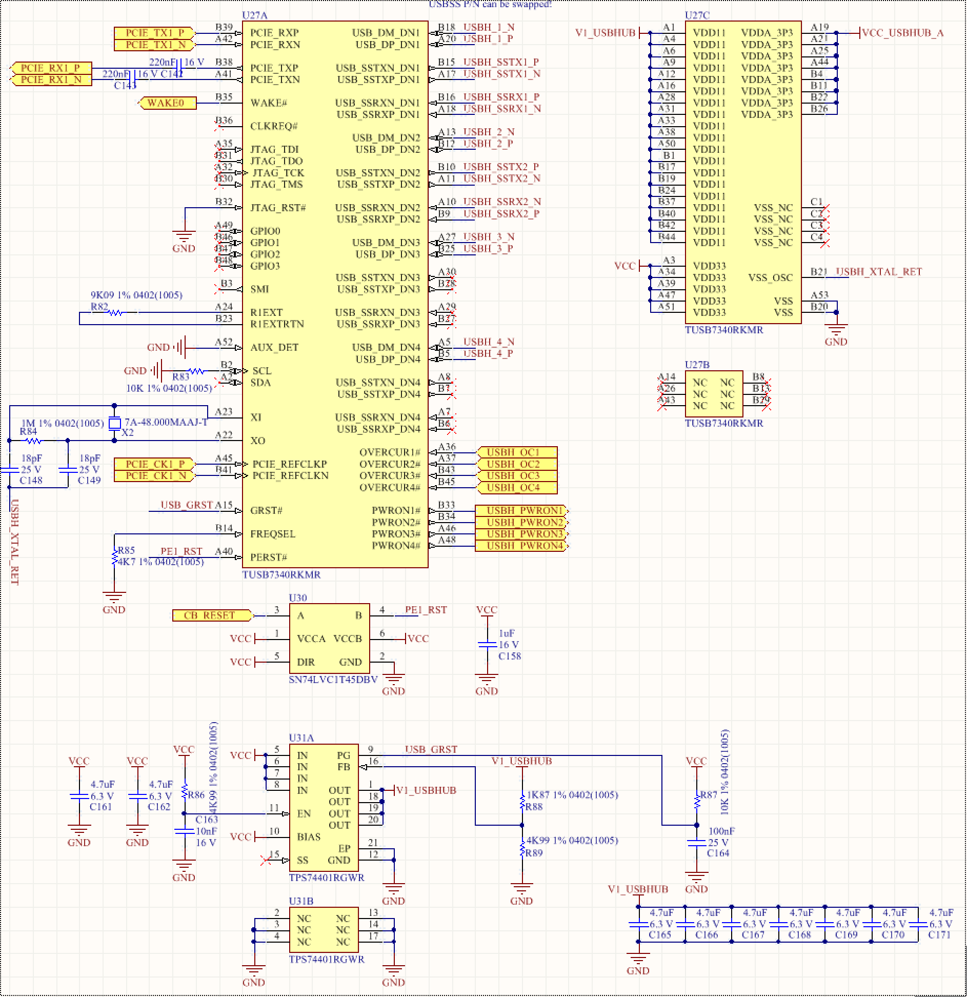
I've attached a photo of my schematic, which is heavily based on the reference schematic.

What might cause this issue?

Thanks! Ben

  • Hi,

    Further details-

    The TPS74401 appears to be operating nominally, outputting a steady 1.100V with 0.799V on the feedback pin.

    I double checked every pin against the EVM. The only tangible differences I can find are:

    - My SDA is floating (although I probed it and it is 0V)

    - I have AUX_DET grounded (short to ground). Is it OK to short to ground or do I need a resistor? Does AUX_DET -> ground actually work, or should I pull it up like in the EVM?

    - I don't have the protection on WAKE# that's detailed in the reference doc. Is it possible that that can cause this issue?

    Please help! I can send further schematics/layout files to an employee if needed

    Ben

  • Hello,

    How much current is it drawing?

    Does the current draw changes with different USB devices?

    You can send your schematic to elias.villegas@ti.com

    Regards

  • Hi Elias,

    It appears to be drawing approximately 500mA on the 3.3V bus (which powers both 3.3V lines and the 1.1V rail, and I believe most of that current is drawn from the 1.1V regulator because it is very hot). Unfortunately I can't get more accurate numbers because it's on a board.

    500mA is based on current going from 41mA to 169mA @ 15V input power when disabling 3.3V power supply, 3.3V power supply is a buck design with > 85% efficiency. There are no other components on that supply at this point.

    This is when there is no USB device connected- adding USB devices doesn't noticeably increase power draw.

    Email sent!

    Ben

  • * adding USB devices doesn't noticeably increase power draw, but I haven't added SS devices yet (SS ports appear to be active as I see switching on TX, USB2 devices are fully functional)

  • Hello Ben,

    I reviewed the schematic and I would recommend at least one 0.1uF capacitor for each VDD11 terminal, the same for each VDD33 and VDDA33.

    That being said, 500mA is not too much, USB2.0 high-current devices will typically draw up to 500mA continuously.

    Did you connected the thermal pad to ground? Do you have vias connected to a solid ground plane on the thermal pad?

    Regards.

  • Hi Elias,

    I thought it might be capacitance related too, so I probed the VDD11 pins on the package and see maximum 20mV oscillation on a ~50ns time period (infrequently), so I don't think that's the issue.

    Thermal pad is connected to ground on Mid Layer 1 with 16 vias, I included layout prints with the schematic.

    500mA doesn't include any power to devices- it's just the TUSB7430. The package is reaching over 90C in air with no devices connected (according to our thermal camera). So I think something must be wrong- the EVM certainly doesn't get that hot.

    Ben

  • Hello Ben,

    Please check if terminals WAKE# or CLKREQ# are oscillating.

    Can you connect the pull-up and capacitor to GND on these terminals?

    What is the failure rate? (failure=TUSB7340 heating up)

    I am asking for someone local from TI.

    Regards

  • Hi Elias,

    No oscillations on WAKE#. Have tried with it pulled up (stable at ~3.28V) and pulled down (stable at ~10mV), same behavior in both cases.

    CLKREQ# is NC in my design, just like in the EVM, and I can't access it because it's on the interior row. Do you think that's a likely cause? Should I consider spinning the board to bring it out?

    We have 6 prototypes which all experience the exact same symptoms. They were all manufactured at the same time, so it's possible there was an issue during manufacturing, but it seems unlikely.

    Thanks,

    Ben

  • Hi Ben,

    I know you worked on it a long time ago but I'm facing the same problem with the 7320 so I wonder if you were able to find the cause of your problem. If you were able to resolve the problem, could you explain how you were able to fix it and what was the cause.

    Thanks, you're help would be appreciated

    Christian
  • I have the exact same issue as Ben. Looks like the 7340 is working but it gets very hot. I followed the EVM schematic exactly as Ben did. Seems several people have this issue. If there is a solution, it would be good to let people know.

    Thanks,
    Chris
  • Hello Chris,

    Could you please send us your schematic for review?

    Regards,
    Roberto
  • Hello Roberto,

    I am attaching the schematic to this reply.  I have a few notes:

    - I added a pullup 10k to nGRST.

    - I am using the board 3.3V and not PCIE 3.3V

    - I have 5V_USB_EN tied high so it turns on at power up.

    I can power this on, read the PCI bus and see the TI controler. I can plug in a USB thumb drive and I get a few "device not accepting address , error -62" but then it connects and I can see the files on the drive.  I'm using Ubuntu.  I can transfer files with no issues.

    Besides the error -62, the main issue is the 1.1V regulator and the TUSB7340 case temperature are approaching 100 degC even with a small heat sink attached?  Even without any USB device attached, they are still 90 degC?

    Thanks,

    Chris123-002480.pdf

  • I will like to first address the issue in two parts. Current draw and getting hot.

    High Current Draw, This device does draw high current in normal operation depending on the number of ports connected and depending on the speed.

    But if the ports are disconnected, the current draw should not be high. If you do see high current with nothing connected and you see TX differential toggling at ss port, the device could be in compliant mode. But there needs to be specific test fixture and sequence to get the port into complaint mode. TX will however be doing a common mode signalling to do rx termination detect this should not take too much current.

    Another possibility is I/O contention, This will typically show up on 3.3V current and not 1.1V current.

    Another possible cause is partial shorts cause by such things as solder bridging. This package with a multi-row QFN. Unfortunately this comes with some manufacturing challenges. This require some care in the landing pad and stencil design to avoid solder bridging during manufacturing. We have seen this issue with some board shops. Here is a document that describes the guidelines SZZA059  on ti.com.

    There is another scenario where the thermal pad (in this device it is actually an electrical ground to not only dissipate heat but also to get the ground current to flow through the board. It is critical that the ground contact be good so the device operate properly and not stay in an unknown condition drawing larger than expected current.

    As for getting hot,

    This device should not get hot with 1A current as the package is designed to support that kind of current. However, if the thermal pad has soldering issue that has excessive voids it will cause an IR drop and produce excess heat. typically, you can have your board shop to do high res X-ray and look for solder voids under the package. x-ray can also spot resistive shorts due to solder bridging. The above guideline documents will help with this soldering issue as well.