This thread has been locked.

If you have a related question, please click the "Ask a related question" button in the top right corner. The newly created question will be automatically linked to this question.

Debug DP83848J (no MDI communication)

Other Parts Discussed in Thread: DP83848J

Hi there,

I am debugging DP83848J with Xilinx Spartan 6 and now find no data read from MDIO port (always reads 0xFFFF, indicating MDIO always pulled high during reading).

The snapshot of schematic design is shown as below:

Since I directly borrowed this part of design from AVNET LX9 MICROBOARD and carefully double checked it with the  datasheet of DP83848J, I have no idea of what could go wrong with schematics.

What I checked after looking through a couple of related posts about DP83848 in this forum:

1) Pin 19, 30, 16(PFBOUT, PFBIN2, PFBIN1) have been all tied together. Their voltage I measured is around 1.8V, which is correct.

2) RBIAS (pin20) has a voltage around 1.2V, which is also correct.

3) MDC(around 2MHz) and MDIO write has a good timing observed by oscilloscope. During MDIO's supposed input from DP83848J, it stays at 1. Op code, device address, and reg address are correct during MDIO read, observed by the oscilloscope. In fact, I have a good confidence in MDIO operations driven by the internal EMACLITE of spartan 6.

4) RX0~RX3 are pulled up internally inside Spartan-6 LX16, so the PHY address is 0x1E(0b11110). In fact, I tried all the 32 PHY addresses but have no success.

5) Before any MDIO operation, the PHY_RST_N is pull down to 0 for at least 4us. This make sure that the default PHY address is set to 0b11110, if DP83848J is working properly, before any MDIO read/write.

6) All the power supply pins are measured and their voltage level stays at 3.3V.

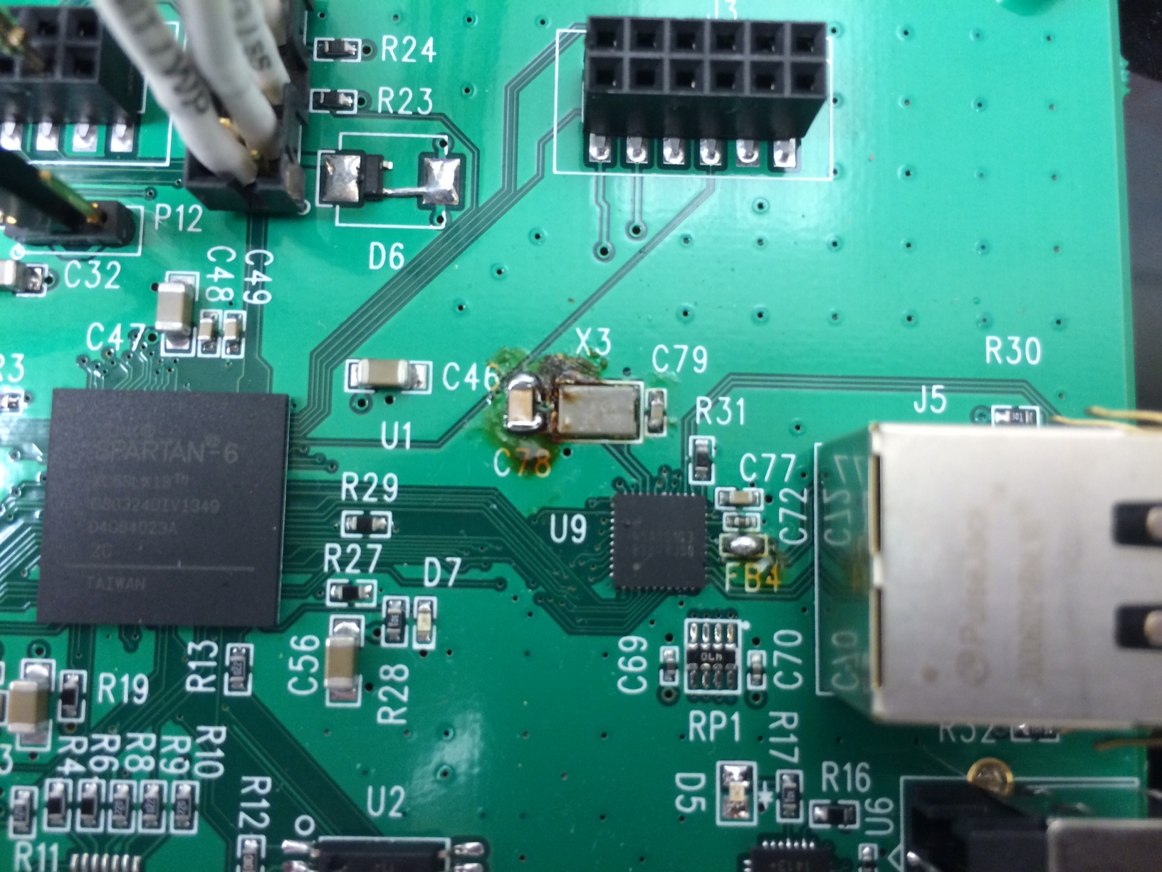
One thing I suspect is the crystal installed for DP83848J. It part number is FQ5032B-25 (CRYSTAL 25MHZ 20PF SMD). As you can see in the schematic design, C78 and C79 are of 20pF. But on the datasheet of the PHY device, it is suggested that the load capacitor should be b/w 25 and 40pF (Table-9, page 34). The crystal is probably the only part that is different from the original design of LX9 microboard. What is more, I probed RX_CLK(pin31) and TX_CLK(pin2) but observed no clock output at all. I guess that might be the cause of the problem but I am not sure at all. 

As far as I have learnt, MDIO communication should be always ON no matter whether MII communication is set up properly or not. But I am not sure if other factors might effect MDIO communication or not, e.g, the Crystal.

Please let me know if you have any thought on the debugging. Thanks in advance!

  • If you are not seeing any activity on TX_CLK and RX_CLK, you are right to be concerned about the X1 reference clock.  The crystal datasheet indicates that the load capacitance (CL) for the FQ5032B-25 should be 20pF.  Fox Electronics has a great application note on crystal parameters, including calculation of the discrete load capacitors based on the CL datasheet value, at:

    http://www.foxonline.com/pdfs/xtaldesignnotes.pdf

    Based on this, I suspect that your discrete load capacitors should be closer to 35-40pF. 

    I would also suggest removing the ferrite bead FB4 or increasing the capacitance of C72.  The 0.22uF capacitor probably cannot sufficiently de-couple that supply.  It may be oscillating and causing problems for the analog circuitry supplied by the AVDD33 pin. 

    Patrick

  • Hey Patrick,

    Thanks for your suggestion. It DID solve part of the problem. But something else I could not understand just happened after I made changes based on your advice.

    Here is what I did and then observed today:

    1) Replace C78, C79(the discrete load capacitors for FQ5032B-25) with 33pF, 50V capacitors. Remove FB4 and replace it with an 0 ohm resistor.

    2) Go back to test DP83848J in the previous way. No thing happened.

    3) Start to check the voltage levels of important pins. When checking the voltage levels of pins of C78, C79(connected with FQ5032B-25) with the probe of multimeter, the SPEED LED of RJ45 is on. This indicate that part of DP83848J is starting to work after probe touched the non-GND pins of C78 or C79. 

    4) Check the RX_CLK and TX_CLK with oscilloscope. They start to generate clocks.

    5) Some operations will turn the SPEED LED off and stop DP83848J from clocking as well: reset DP83848J, download code into the microprocessor built inside Spartan 6, etc. Some are related with DP83848J, others do not seem so. But it just happened.

    6) Whennever SPEED LED is off as well as DP83848J stops clocking, touching the non-GND pin of C78 or C79 (with probe or simply a finger) will actually fix EVERYTHING. With my finger pressed on C79's non-GND pin, DP83848J could pass the loop-back test generated by Spartan-6. This test simply set DP83848J into loopback mode, and then receive the loopback data from DP83848J to see if it matches with the data already sent. So simply speaking, everything is fine now, only if you have something touching on one of C78 and C79.

    7) I also tried difference combinations of C78, C79. For example, 33pF and 33pF, 22pF and 33pF, 47pF and 33pF. Based on the design note from Fox Electronics, these gives load capacitance at 16.5pF, 13.2pF, and 19.4pF. If Cstray is 5pF, the load capacitance will be 21.5pF,  18.2pF, and 24.4pF, respectively. However, what I observed stays the same. 

    I tried my best to describe what I saw today and hope you understand what is happening. This is weird to me. I initially suspected that by touching the load capacitance is somehow changed to the correct value. But what you can see here is that all those combinations of C78 and C79 just gives you the same thing. Could that be a soldering problem? I doubt it because I remove those load capacitors and solder them back on multiple times while trying out the difference combinations.

    The truth is that this is probably beyond my knowledge and I hope somebody here could give a hand. Thanks in advance!

  • Hi Xuemeng,

    From what you described above I would think that this is a contact issue on the board, but with all the soldering of different combinations I would think that there would be a solid contact for one of them. 

    When you apply pressure to the caps does your finger touch the crystal? Have you checked to make sure the crystal has a good connection?

    Is it possible for you to provide a photo of the board?

    Cheers,

    Ross

  • Hi Ross,

    Thanks for you reply.

    No, I did not touch the crystal. Nor did I apply much pressure to the caps, simple using the tip of a probe (shown in Fig.1) to get a contact with the caps. Only one touch is needed for reviving the crystal and PHY, that is the SPEED LED is on after one touch. However, another operation, which may not even directly talk with PHY, (e.g, MDI read, PHY reset, or just downloading code into spartan 6 microprocessor) will turn the LED off, which indicating that PHY is not generating RX_CLK or TX_CLK. To complete the loopback test driven by spartan 6, I need to continues touch the caps during the test, with either a finger or a tip of probe.

    Fig 1

    I will check the connection of the crystal. But I doubt it is the cause of the  problem since I did not touch it whether the loopback test was successful or not. Fig 2 is the photo of the board. There is a mess around C78 and C79 since I did soldering a multiple times there. But each time, I did check the connection of the soldering with multimeter.

    Fig 2

    Hope this helps you to understand this problem better.

  • Ross, 

    This is what I found out today.

    1) If I use a non-conductive object, for instance a plastic stick, to touch the caps, RX_CLK/TX_CLK won't come back. Neither is SPEED_LED back on. This works only when I use something conductive, such as a finger and a probe of multimeter. This indicates that the problem is probably not a contact issue.

    2) When clock is off, the 3.3V power supply has a current running at around 110mA. When it is back on, the current is 130mA. If the loopback test is successful, the current will be changed to 170mA.

    -Sean

  • Another update:

    Now with C78=47pF and C79=22pF(suppose Cstray = 5pF, this makes CL = ~20pF), RX_CLK is around 41MHz and TX_CLK is around 23MHz when they are active.

    Shouldn't the frequencies of RX_CLK and TX_CLK the same?

    Does this have somethng to do with the problem with clock generating?

    Please let me know. Thanks in advance!

  • Another update that might be interesting:

    A friend of mine suggested that by connecting the non-GND pin of C78 to a conductive wire it is similar as adding an antenna to this cap. So I soldered a wire to C78, as shown in the picture below. The result is interesting:

    1) With a certain length of the red wire, the loopback test is as successful as that with my finger touching C78 all the time.

    2) After the success, I went on to cut the wire shorter. Loopback test failed: clock is running( but at a frequency of 40MHz), SPEED LED is on, but spartan 6 did not hear back from PHY. And when I held the other endpoint of this shorter wire, the loopback test passed.

    Can you explain what happened? This is certainly beyond my knowledge now...