


Other Parts Discussed in Thread: DP83848I
Hello,
i have a few questions to the DP83848IVV. My situation: I tried to evaluate my own board with the DP83848I(VV) and AT32UC3C164C microcontroller from Atmel (µC is sitting on a Atmel STK600 Evaluationboard).
The DP83848I is on an extern own layouted board. Supply Voltage and Ground is used from the STK600. Signalconnections from own board to STK600 are realized with some usual wires (10cm long - i know it is not ideal for xx MHZ signals). The schematic of my own board is referred to the EVK1100 & EVK1105 evaluation boards from Atmel. I read in some forum posts about the DC checkpoints and checked them out:
Pin Description DC Value MY DC-VALUES (DP83848I-Board referred to the connected STK600 Ground)
15 AGND 0 Volts 1,3mV
18 PFBIN1 1.73 to 1.8 Volts 1,725V
19 AGND 0 Volts 1,3mV
22 AVDD33 3.3 Volts 3,26V
23 PFBout 1.73 to 1.8 Volts 1,725V
24 RBIAS 1.19 to 1.2 Volts 1,183V
29 RESET_N 3.3 Volts 3,26V
35 IOGND 0 Volts 1,3mV
36 DGND 0 Volts 1,3mV
37 PFBIN2 1.73 to 1.8 Volts 1,725V
47 IOGND 0 Volts 1,3mV
48 IOVDD33 3.3Volts 3,26V
The Resistor Values are okay: RBIAS=4,87k and MDIO Pullup=1,5k.
Reset Pin got also 10k Pullup.
So here are the first part of my questions:
1. Is the PFBIN1/2 / OUT voltage critically low?
2. Is the RBIAS voltage critically low?
3. Is it necessary to connect the Reset Pin to a PullUp?
I measured some additional testpoints because my focus was also on my used CMOS-OSC (frequency).
The used oscillator is connected to Pin 34 (X1). I used the 7W-50.000MBA-T CMOS-Oscillator from TXC. It is a different one than the CFPS73 (HCMOS) which is chosen by ATMEL on EVK1100/1105.
Pin Description DC Value MY DC-VALUES (DP83848I-Board referred to the connected STK600 Ground)
34 X1 ?? ~1,5/~1,6V (after removed OSC output-pin !)
On the removed output-pin of this CMOS-Oscillator there was a DC-Voltage(~1.7V) with a 50MHZ AC-signal. The low-level was ~1.2V and high-level was approx 2.2V.
Second part and very important part of my questions:
4. Is the CMOS-OSC damaged?
5. Why is there a DC-Value at PIN 34 (X1)?
6. What High/Low-level is needed to get a correct oscillation for the DP83848IVV?
In the attachement is my schematic. Reset and PWR_DOWN/INT Pin are connected through wires afterwards (because i forgot them). RESET_N Pin got a PullUp to 3,26V Supply and the PWR_DOWN/INT Pin is directly connected to my microcontroller pin.
Hint: RBIAS is 4.87k (not 4.868k which you see in schematic) 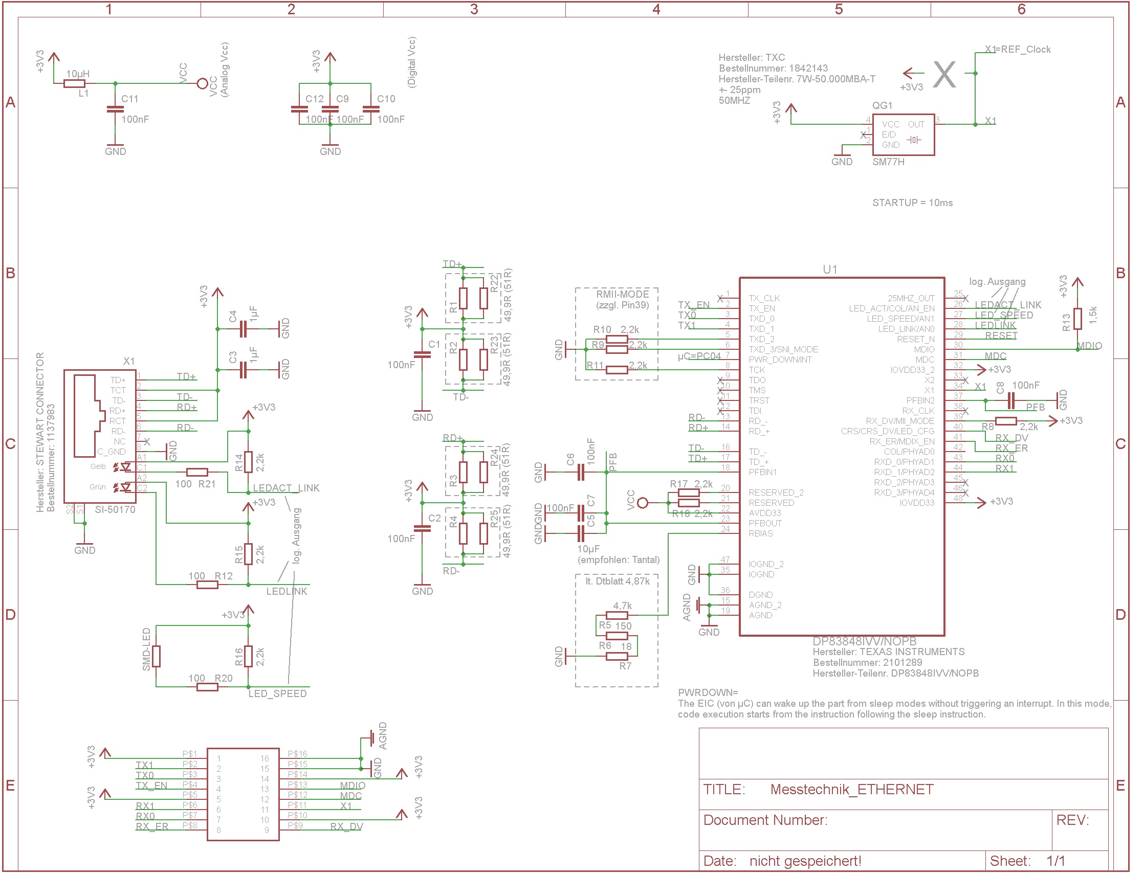
Third and last part of my questions:
6. The resulting values of my resistors on Pins TD+/TD- ; RD+/RD- have always value ~1Ohm when i measure from RD- to TD+ or TD+ to TD- or RD+ to TD- ord RD+ to RD- because of the magnetics on the middle tap. These values are okay i think?
I hope somebody can help and support me.
Best Regards
Sebastian

