A related question is a question created from another question. When the related question is created, it will be automatically linked to the original question.
If you have a related question, please click the "Ask a related question" button in the top right corner. The newly created question will be automatically linked to this question.
how to configure all the registers of dp83640..? do i have to write any code or it can be done through hardware means..?? I am interfacing this chip with fiber optic transceiver AFBR-5803Z..
okk.. I am not getting how to write in these registers in practical... i.e., how to configure these registers in practical..?? do i have to use some software or by hardware means the registers can be configured..??
There is a section in our datasheet dedicated to the serial interface (MDIO) that is used to read and write to the PHY registers.
Your CPU/MPU or controller will need to have the MDIO interface to communicate.
If this is not possible, it is highly recommended that you use a hardware means of setting the registers.
Hardware configuration is done by strapping.
When the phy is powered on or there is a hard reset, the voltage read on certain pins of the chip will be stored (latched) and set the PHY registers. The pins with this strapping option are labeled in the DP83640 datasheet (section 3).
In this section you will see that there are 2 pins required for hardware setting fiber mode.
These pins are AN0 (LED_ACT) and FX_EN_Z (RX_ER).
RX_ER has an internal weak Pull-Up resistor that disables Fiber mode. To force the PHY into fiber mode you will need to have a 2.2Kohm resistor connected from the RX_ER pin to GND.
LED_ACT has an internal weak Pull-Up resistor that forces the PHY into full-duplex operation. If you require a half-duplex operation you will need to connect a 2.2Kohm resistor from the LED_ACT pin to GND (Pull-Down).
I am also facing the issue of DP83640 not pinging in fiber mode.
I am using AM3354 processor and interfacing DP83640 chip over RMII mode. DP83640 is prefectly pinging while it is used in COPPER mode.
Hardware Strapping are as belows:
For Copper mode, LED_ACT (Pin 26), LED_SPEED(Pin 27), LED_LINK(Pin 28) are individually pull up using 2.2K resistor and RX_ER(Pin 41) is also pull up using 2.2K resistor. IN copper mode, DP83640 is pinging properly and link is also detected in linux console.
For Fiber mode, LED_ACT is pull up using 2.2k and RX_ER is Pull down using 2.2k while LED_SPEED and LED_LINK pins are floating. We are using AFBR5803TZ fiber transceiver and SCto ST fiber multimode cable. But, we are not able to ping in fiber mode. Link is also not detected in linux console.
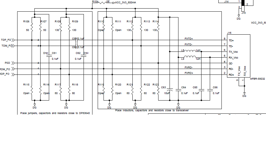
Please find below schematic of fiber optic connector. Please suggest the solution.
AN1 is already connected to PSD line Pin 4 of Fiber transceiver.
Currently, i am not reading register of Phy as i thought i can manage fiber mode just by hardware strapping registers. Also, for copper i am managing the same way.
Can you let me know what should be the electrical voltage levels over TX and RX lines of fiber transceiver? Is this can be issue. Registers values we used are as per schematic already attached in previous update. I have tried changing values of R117, R118, R121, R122 from 80 ohms to 82 ohms. But no improvement.
One observation i found is as per below.
If i keep my development board in Power ON condition and then just give power reboot to my 100baseFX to 100BaseTx media convertor, i can see below messages on kernel console of my board.
Link is Up - 10/Half
eth0: Link becomes ready
But, still cannot ping while my converter shows FX 100Mbps led and FX link signal available.
And, if i give power reboot to my board, above messages do not appear on console and shows link not ready.
Your earliest post mentioned that both Pin 27 and 28 are floating, hence the recommendation to connect 27 to Signal Detect of Optical transceiver.
While Phy is configured in Fiber, we shall only see 100M as 10M is not supported. I would need to see Status register 1 and 10 to understand status of Phy in both scenarios: a) Link Partner power cycle, b) DP83640 power cycle.
I am checking the RX signal on CRO after pinging my development board from my laptop. But, i am not seeing any data signal on CRO. My RX lines are at continous 2.2V but no data coming on RX pins of Fiber transcevier AFBR5803TZ connector, checking on CRO.
Also, can you guide me how to check status register 1 and 10 in kernel. Do i need to read in dp83640 kernel device driver.