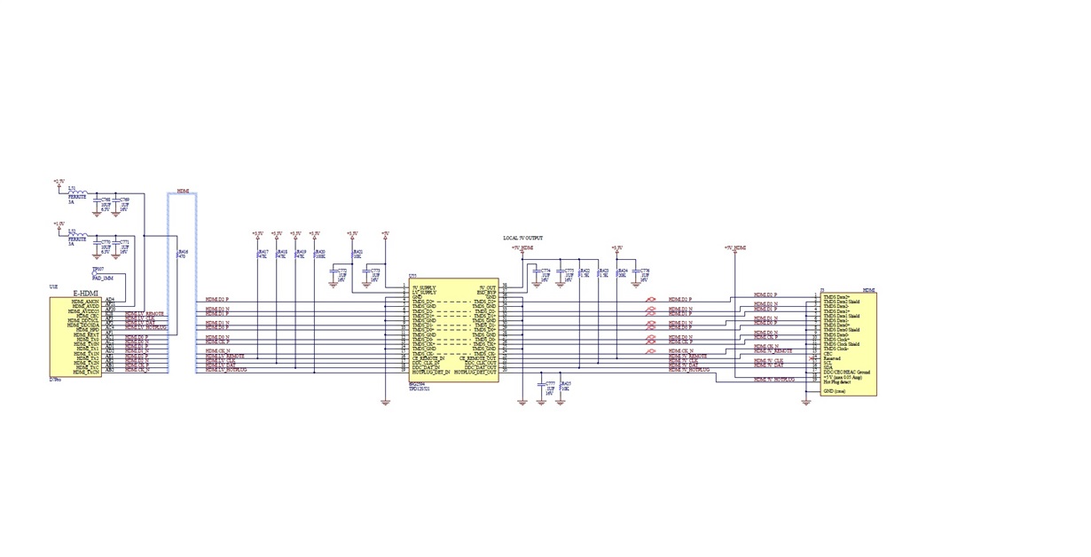
We are doing some HDMI certification testing in on our equipment and it appears we are failing one part of the spec that states there be <50pF at the HDMI connector on the HDMI DDC_DAT and DDC_CLK lines. We are measuring around 34nF on our designs which come through either a TI TDP12S521DBTR or CM2020 On-Semi device.
First question on the resistor pull-ups we have on the DAT and CLK lines what Power Supply rail should these be pulled up to? We have them pulled to the 5V_OUT side and there is a .1uF decoupling cap recommended on this rail but this appears it would then violate the HDMI spec for <50pF on these lines. We saw in experimenting when we removed our 1.8k pull ups on these lines our designs dropped down to 14pF from 34nF so this does appear to be an issue.
Second question would be since our designs should the HDMI source and will not have an EEPROM do we even need the pull up resistors populated on the DAT and CLK lines? On an ON-SEMI dataheet of the equivalent part the layout example they show the DAT and CLK traces with a pull ups and then going to an EEPROM which we don’t have the EEPROM. In our design the HDMI DAT and CLK lines come from the connector through the TI TPD12S521DBTR or CM2020 On-Semi device and then into our custom ASIC with no EEPROM.


