This thread has been locked.

If you have a related question, please click the "Ask a related question" button in the top right corner. The newly created question will be automatically linked to this question.

TLK105/TCA9406 MDIO/MDC access issue

Other Parts Discussed in Thread: TCA9406, TLK105, TLK105L

Hello,
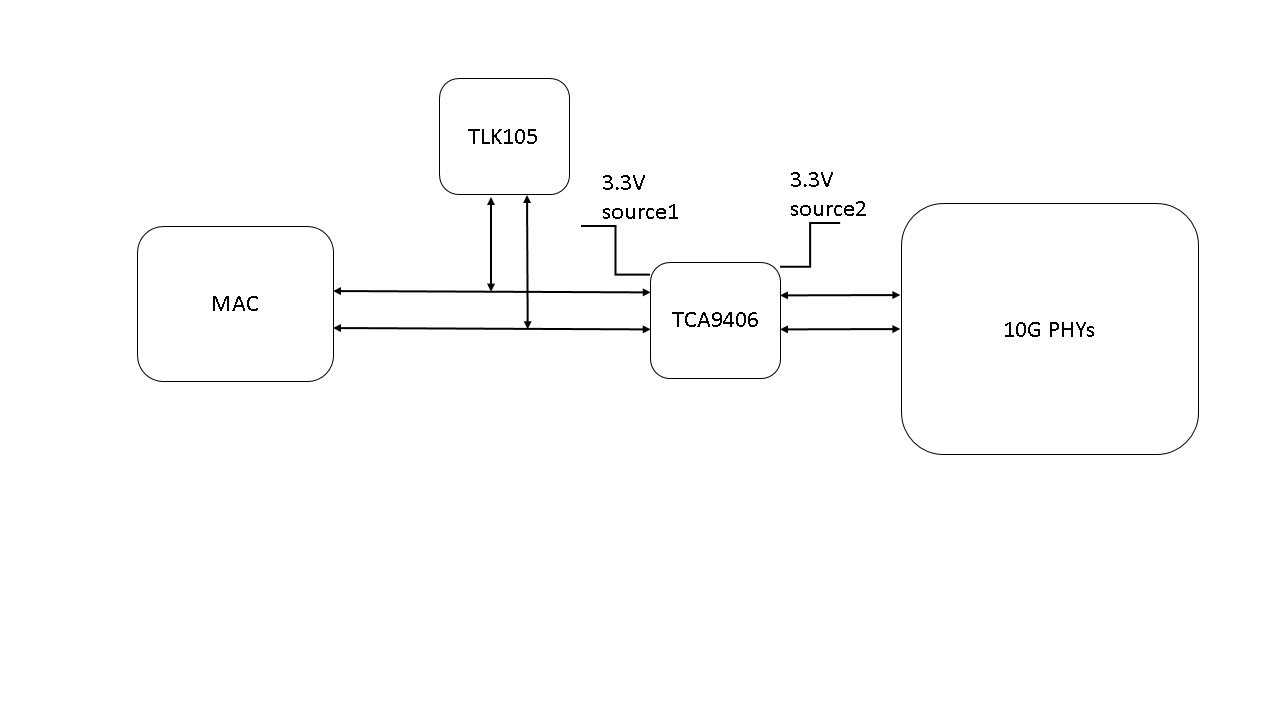
In one of our design we have used TCA9406 as a level-translator for MDIO/MDC signal. Please find the below system description. We have the following observations:

1. When 3.3V source2 is turned off, the MAC to TLK105 interface is working properly. But with both 3.3V sources that interface is not coming up.


2. When both the power supplies are ON and when we probe the MDC signal at the input of TCA9406(signal going to TLK105 PHY) the interface is working properly.


3.When the SCL2 and SDA2 pins on the 3.3V source2 is lifted, the MAC to the TLK105 interface works fine.


I would like to know how the interface works properly on probing.(mere touching of the trace with the probe irrespective of whether the probe-ground is connected or not)
We have 2.21k pull-ups on both signals (3.3V source1) and 4.99K pull-ups on both signals(3.3V source2). We have used 200K to connect the OE pin to the 3.3 source1.

The frequency of SCL is 200KHz.
We are not using TCA9406 for any voltage translation. We have used TCA9406 as the MAC and 10G PHYs are in different power supplies.(same voltage different current)


  • Sreenuj,

    What is your definition for proper operation? By this do you mean you are able to correctly read the registers?

    How many 10G PHYs are connected to the MDC / MDIO? For what PHY addresses are the TLK105 and the 10G PHYs configured? What value of pull up resistors are used for the MDIO pins of each PHY?

    Patrick
  • Yes by proper operation I meant correctly reading the registers.
    I have three 10G phys- 2 quad phys and one dual phy.
    TLK105 is configured for phy addr 16.
    10G phys with - 0,1,4,5,6,7,8,9,10,11
    TLK105 has 2.21k pullup on mdio signal and 10G phys have a pullup of 4.99k on the mdio signal shared by them.
  • Hi Sreenuj,

    Can you see the MDIO and MDC lines toggling when you have both Source1 and Source2 on?

    Would it be possible for you to change the 10G phy that is addressed as '0' to '2'? The reason being is that typically PHY address of '0' is a broadcast address.

    Regards,
    Ross
  • Hello Rose,

    When both source1 and source2 are on, I can see my mdio and mdc toggling  but when I probe, my MAC to TLK105 interface is working properly(I continuously read and print the PHY ID). So I don't know the state of my MDIO and MDC signal when the MAC to TLK105 interface is not working.

    It is possible to change the 10G phy address from 0 to 2.

    But the problem w.r.t  TLK105 persist even if I am not writing anything to the 10G PHYs. I would like to know in what way changing the phy address helps?

  • Hi Sreenuj,

    I was reading through your original post again found something that I would like more clarification on.

    You said that both signals on source1 are pulled high through 2,2Kohm resistors. MDC should not have a pull-up only MDIO. Can you verify? 

    Regards,

    Ross

  • Hello Rose,

    In our actual design we didn't have the pullup on MDC. Still the issue was there. Since we found on probing the interface is working, we doubted the absence of pullup, so we mounted it to confirm, but it didn't make much difference. 

    Without pullup on MDC signal also issue exist. In my post I added pullups on both signals as it was my last setup.

    Regards,

    Sreenuj

  • Hi Sreenuj,

    This is very odd behavior to only have the MDIO/MDC working when you probe. Please remove the pull-up on the MDC line, a pull-up should only be on the MDIO line.

    Can you send me a schematic and board layout? If you prefer to not send this information on E2E I can give you my email.

    Regards,
    Ross
  • Hello Rose,

    As I mentioned before, the problem persist even when there is no pullup on MDC signal.
    Kindly provide your mail id for sending the TLK105/TCA9406 schematics and board layout.

    Regards,
    Sreenuj
  • Hello Rose,

    I would like to add one more detail.
    Currently I am using a signal to control the TCA9406 translator. Whenever I access the TLK105 PHY, I will disable the TCA9406 and TCA9406 is enabled only when I access the 10G PHYs. With this configuration I am able to access both PHYs(10G and TLK105) with limitation of simultaneous access. The pullup configuration is: pullups on MDIO signals on both side of TCA9406. No pullups on MDC signals.

    Regards,
    Sreenuj
  • Hello Rose,

    We have already tried that once.  I have pin lifted the mdc/mdio  going to 10G and I was able ti access the TLK105 properly.

    Also we have tried removing TCA9406 and shorting the both side mdc/mdio signals. But this didn't help.

  • Hi Sreenuji,

    Then is seems like the 10G PHYs are somehow in contention with the TLK. Please send me the name of the 10G part.

    Regards,
    Ross
  • Hello Rose,
    Please check your email. The schematics and layout if required will send you on 16th.
  • Hi Sreenuj,

    I just reviewed your schematic and it looks clean. Since we know that the issue is occurring only when both types of PHYs are connected can you try figuring out which of your 10G PHYs is having issue with the TLK? 

    Regards,

    Ross

  • Hello Rose,

    In what way i will figure out the fault? Can you suggest any methods?

    I have tried with keeping the 10G phys on reset. Still the issue was there. None of the 10g phys respond via mdio-mdc other than the assigned address.Only when I power down the 10g phys tlk105 responds.I am out of ideas to try, please do suggest.

    Whether the issue seems anyway connected with the mismatch in input impedance of tlk105 and tca9406?

    Regards,

    Sreenuj

  • Hi Sreenuj,

    I am confused about what you mean by "None of the 10G PHYs respond via mdio-mdc other than the assigned address."? Do you mean that the PHYs will not respond to any commands unless you specifically address them? To communicate with the PHYs, you must specify the PHY you want to communicate with.

    I am curious as to which 10G PHY is causing the issue. Is there a way for you to only have one 10G PHY on the line at a time with the TLK? This way we can figure out if it is one specific 10G PHY that is in contention with the TLK or some other issue.

    Regards,

    Ross

  • Hello Rose,
    Sorry for the confusion. I meant that none of the 10g phys responded for the address of 16, which is of tlk105.
    There is no way to isolate within 10g phys.
    By contention what exactly you mean?
    1. Is it any signal from mdio-mdc pins of 10g phys interfering with tlk105 communication with mac?
    2. Since on probing the mdc signal tlk interface works fine, something from the probe is helping my signal. That something is helping my signal to reach the tlk without any distortion.
    3. When I was reading the phy id of tlk continuously, sometimes i get correct value,sometimes all 'f's, sometimes completely random value. Since phy id is a read only register, I presumed that the the only way to get an invalid value is when some other phy responds. But when I put the tlk in reset and tried to communicate with 10g phys using address of tlk, none of them responded.
    4. My quad 10g phys are having clause 45 registers and dual 10g phy have both clause 22 and clause 45 registers. Does this will cause any issue?

    Regards,
    Sreenuj
  • Hi Sreenuj,

    Since the 10G PHYs are not responding to the register address 0x16 when the TLK is reset, I do not think there is issue with both TLK and any one of the 10G PHYs responding at the same time.

    What could be happening is that there might be a strong pull-up resistor on the MDIO line and the TLK might not have the drive strength to force the MDIO low. Have you tried increasing all the pull-up resistor values on MDIO?

    The TLK105L is also clause 45 capable so there should be no issue with that.

    Regards,
    Ross
  • Hi Rose,

    I have put a 10K on MDIO signal instead of 2.21K and 4.99K. Still the issue exist.

    Regards 

    Sreenuj

  • Hi Sreenuj,

    Maybe your CLK signal is a bit noisy. Since you see that the TLK can communicate fine when you probe, have you thought about adding a capacitor on the CLK line? The probe will add capacitance as you are aware. Make sure though that you don't attenuate the signal too much, but it does seem like the added capacitance you are introducing helps stabilize the CLK from your source.

    Regards,

    Ross

  • Hello Rose,

    The MDC clock was running at 2.5MHz. When I reduced the clock frequency to 10KHz, the issue got resolved. Hopefully some SI issue.

    Regards

    Sreenuj

  • Hi Sreenuj,

    Glad that you found a workaround. The device spec is for 25MHz MDC. I am surprised that you get it to only work at this lower frequency.

    Please let me know if you end up doing any more measurements on your setup.

    Regards,
    Ross