Hello,
appriciate your help! The last post can not found again. I do not know why, so repost it again. And Thanks a reply from Ross. I had supplement further details in this post about loopback tests.
We use C6747 and TLK105 (hardware),DSP/BIOS5.42 and NDK2.0(Software) for ethernet communiction. The development environment is CCS5.5.The ndk/src/hal/evm6747/eth_c6747/cls_mdio.c (and cls_mdio.h) had been reconstucted for TLK105.However no data transmited to pc and no data received on DSP side. The deep observation are:
1) PHY link is setuped, but no data received on dsp side and pc side;
2) Only one transmit action on dsp is observed in void HwTxInt(void) function in file etherdriver.c;
3) Can not found HwRxInt(void) function (in file etherdriver.c) was trigered;
4) The dsp EMAC reg RXALIGNCODEERRORS and NETOCTETS is not zero;
5) MDC and MDIO function is normal, and can write and read the PHY reg;
6) The data signal of TXD[1:0] and RXD[1:0] between the MAC and PHY can be observed;
7) The pin PFBOUT is 1.56v, the pin RBIAS is 1.22v;
We had applied PCS OUT loopback, DIGITIAL loopback, FAR END loopback, ANALOG loopback TESTS. result is as follow:
1) PCS OUT loopback passed, I can observed the HwTxInt(void) function and HwRxInt(void) function trigered;
2) DIGITIAL loopback passed;
3) FAR END loopback passed on PC with PING command;
4) ANALOG loopback failed. is that TLK105 malfunction or broken?
I had reconfigured the ELAST_BUF field of RCRS in TLK105 as 14,2 or 6 bit torlerence, however, it is no help for this problem.
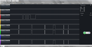
We had captured the signal between DSP and PHY in communication without loopback, the RXER signal is same at all with RXD1. It is very strange. The screenshot is as follow:
I am newbie for ethernet development, cannot find the reason and resolution. Please help me. Thanks a lot!!!
The PHY regs' dump is:
PHY REG BMCR: 1000
PHY REG BMSR: 786d
PHY REG PHYIDR1: 2000
PHY REG PHYIDR2: a211
PHY REG ANAR: 1e1
PHY REG ANLPAR: cc61
PHY REG ANER: f
PHY REG ANNPTR: 2001
PHY REG ANLNPTR: 0
PHY REG CR1: 3801
PHY REG CR2: 104
PHY REG CR3: 0
PHY REG REGCR: 0
PHY REG ADDAR: 0
PHY REG PHYSTS: 17
PHY REG PHYSCR: 108
PHY REG MISR1: 2400
PHY REG MISR2: 2000
PHY REG FCSCR: 0
PHY REG RECR: 0
PHY REG BISCR: 100
PHY REG RCSR: 21
PHY REG PHYCR: 1e
PHY REG 10BTSCR: 0
PHY REG BICSR1: 7d
PHY REG BICSR2: 5ee
PHY REG TXCPSR: 2000
PHY REG PWRBOCR: 0
PHY REG VRCR: 17
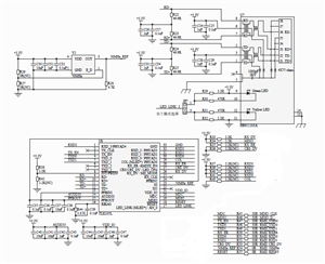
The hardware schematic is as follow:


