This thread has been locked.

If you have a related question, please click the "Ask a related question" button in the top right corner. The newly created question will be automatically linked to this question.

CAN OVER Plastic Optical Fiber

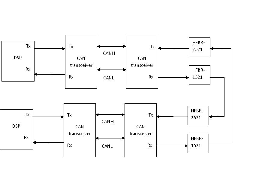
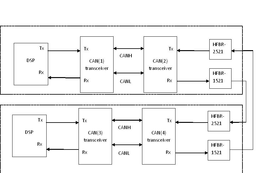
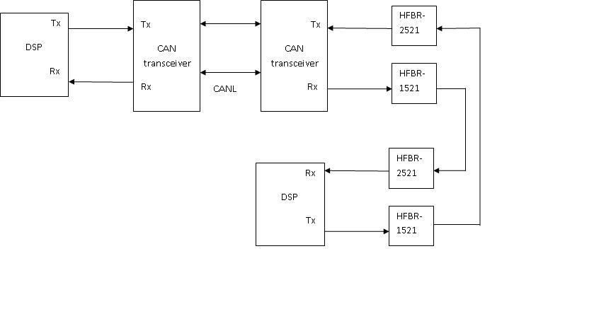
I am working on hardware design for CAN communication on optical media. Since my controller is on one card and my optical transceivers on other card I have first converted CAN TX and RX signals to CANH and CANL by using SN65HVD230D  in my control card and then I have used another SN65HVD230D  to convert back to TX and RX before converting it to optical. I have made two channels and connected both. But it is not working. Can u help me in this regards


  • Hi Bharath,

    Sorry, I am having a little bit of trouble understanding the circuit topology. Do you think you could sketch out either a schematic or block diagram so that we can make sure we understand the issue properly? Also, if you could discuss more about what isn't working it would be helpful. E.g., is there a specific issue you can observe on the TX, RX, or CAN waveforms, some issue with the electrical-to-optical conversion, etc.?

    Regards,
    Max
  • Dear Max

    Please find the block diagram. I have used SN65HVD230D (CAN transceiver). In my application DSP is located on one PCB and optical circuit is on other PCB. So I have used two CAN transceivers before converting to optical. Can u please suggest me will this topology will work. Or I should connect the other end of optical TX and RX signals directly to DSP after converting to electrical signals. 

    Regards

    Bharath Gilla

  • Hi Bharath,

    I don't immediately notice any problems with this set-up. Do you have the ability to probe the signals at each step along the way? I.e., verify that the TX input to the first CAN transceiver is OK, then check the CAN bus waveforms at both ends of the optical link, then verify the RX output at the far end (DSP input)? If not, would it be possible to at least bypass the optical link (so that it is a single CAN bus in a standard configuration) and verify that the DSP communication can work? (If there are any other system-level issues they should then show up; if not, we know to focus on the effects of the additional optical portion.)

    Regards,
    Max
  • Dear Max

     I have given square wave of 0-3V at one of the Tx pin of CAN transceiver(1)[supply 3.3V] and I am unable to receive wave at Rx pin of CAN transceiver(2) when I connect the optical transceiver. But when I disconnect the optical network I was able to receive wave form at Rx pin of  CAN transceiver(2) and also I was able see the LED blinking.  And also I have remove optical circuit and I have shorted the Tx pin of  CAN transceiver(2) to Rx pin of CAN transceiver(4) and Tx pin of CAN transceiver(4) to Rx pin of CAN transceiver(2). I was unable to receive any signal at Rx pin of CAN transceiver(2) when I am sending signal from Tx pin of CAN transceiver(1).

  • Hi Bharath,

    Since you have several different components cascaded between the two CAN controllers (in the DSPs), it is possible that the round-trip delays across the network have become too long for bit-wise arbitration to operate. At which baud rate are you operating, and how do you have the Rs pin of HVD230 configured?

    Regards,
    Max
  • Dear Max

    I have give a square wave of 50hz(Tx pin of transceiver) only which is much less so that the transceiver can easily detect the change in the high low signal. To operate the transceiver high speed mode I have grounded(directly shorted to ground) the Rs pin of transceiver.   

    Max I have seen in the datasheet of Max 3050(page 9 below the table 1) that when simultaneous transmission of the dominant and recessive bits, the resulting bus value will be dominant only .  If this is the case then when I transmit the dominant once from the CAN(1) then my Rx pin of CAN(3) will be at dominant and this is directly connected to Tx pin of CAN(2) which is holding the CAN bus of CAN(1) and CAN(2) permanently to dominant. was my analysis is correct or some other logic was wrong.??

    Regards

    Bharath Gilla

  • Bharath,

    Yes, you are right that dominant signals will take precedent over recessive signals on the CAN bus. The dominant state is actually driven by the transceivers on the bus, while the recessive state is a high-impedance state in which the bus is only weakly tied to a common-mode voltage. So, if any transceiver is outputting a dominant signal, the entire bus will be in the dominant state.

    I didn't understand in your analysis where you mention that RX from CAN(3) is directly connected to TX of CAN(2). This doesn't seem consistent with your above figure (in which the RX signal from CAN(3) connects to a DSP). Am I misinterpreting something?

    Best regards,
    Max
  • Dear Max
    Sorry, its Rx pin of CAN(4) is directly connected to Tx pin of CAN(2)(through OFC). which is holding the CAN bus of CAN(1) and CAN(2) permanently to dominant once we transmit the dominant bit from Tx pin of CAN(1).

    Suppose when we transmit dominant bit from Tx pin of CAN(1) it will be available at Rx pin of CAN(2). It will be transmitted through Optical fiber to Tx pin of CAN(4). due to this the Rx pin of CAN(4) will be at dominant and make the Tx pin of CAN(2) dominant(through OFC) permanently and holding the CAN bus of CAN(1) and CAN(2) at dominant. Dear Max was it correct or am I misinterpreting the working....? 

    Max, I had removed the CAN(3) and CAN(4) transceiver IC's and connected the OFC Tx and Rx directly to my DSP(below block diagram). Its working..

    Regrads
    Bharath Gilla

  • Bharath,

    Yes, I believe you make a very good point. It seems like having both ends of the optical link connect to a half-duplex CAN bus sets up a loop in which the buses get stuck in a dominant state. I don't have a good solution off the top of my head for this, but let me think it over a bit and see if there is any easy way around this.

    Best regards,
    Max