This thread has been locked.

If you have a related question, please click the "Ask a related question" button in the top right corner. The newly created question will be automatically linked to this question.

TLK2711-SP with Common-Mode Choke

Other Parts Discussed in Thread: TLK2711-SP

Hello,

Is it recommended to use an appropriate CM choke in the interface between a TLK2711 driver and receiver to make sure the interface remains balanced and to avoid chassis current? Has anyone used this interface this way? if so, was the filter placed at the driver output or the receiver input? Was the 2711 interface AC or DC coupled? What improvement or issues did you observe?

Thanks

-Ali

  • Hi Ali,

    In datasheet of the TLK2711A (Figure 12), you can check that for AC-coupled mode, the device provides its own internal bias point. Hence, you will not need an external network to set the common mode.

    Regarding to the TLK2711 driver:

    VML drivers are voltage-level compatible with LVPECL.

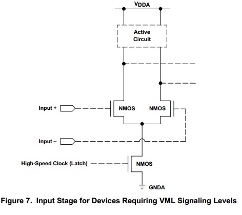
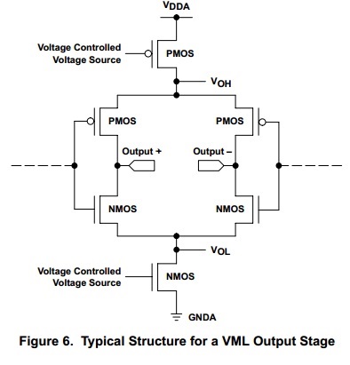
    Like CML, these drivers are implemented in CMOS, but have the advantage that they do not require external pullup resistors, because of the use of internal MOS and PMOS transistors to help drive the falling and rising edges. While VML is not yet as widely implemented as the other drivers, it still remains voltage-compatible with LVPECL signaling levels and has been used in many of TI’s production devices. Current Texas Instruments serial gigabit solution devices that have an integrated VML driver are the TLK2711, TLK3101, TLK1201, TLK2201, TLK2208, TLK3104SA, TLK3114SA, TLK3104SC, TLK4010(1), SLK2501, SLK2511, SLK2701, SLK2721, and the SLK2504.

    Below you can see the input/ouput stage (typical structure):

    Regards!

    Luis Omar Morán Serna

    High Speed Interface Group

    SWAT Team

  • I was wondering whether adding a CM choke will further help to balance the interface even while it is AC-coupled? Has anyone implemented or tested this interface with CM choke?

    3 more questions:

    1. Are there test measurements of chassis/structure current between a TLK2711 driver and receiver a few meters apart and in two different metallic electronic assemblies each being powered with a different power supply (the return of the supplies are tied to metallic structure that connects the two metallic electronic assemblies)? 

    2. Figure 12 of TLK2711A datasheet shows the series capacitors at the receiver input, I am assuming there are similar capacitors at the driver output? Is there an app to show what the recommended value of these capacitors should be at various data rates?

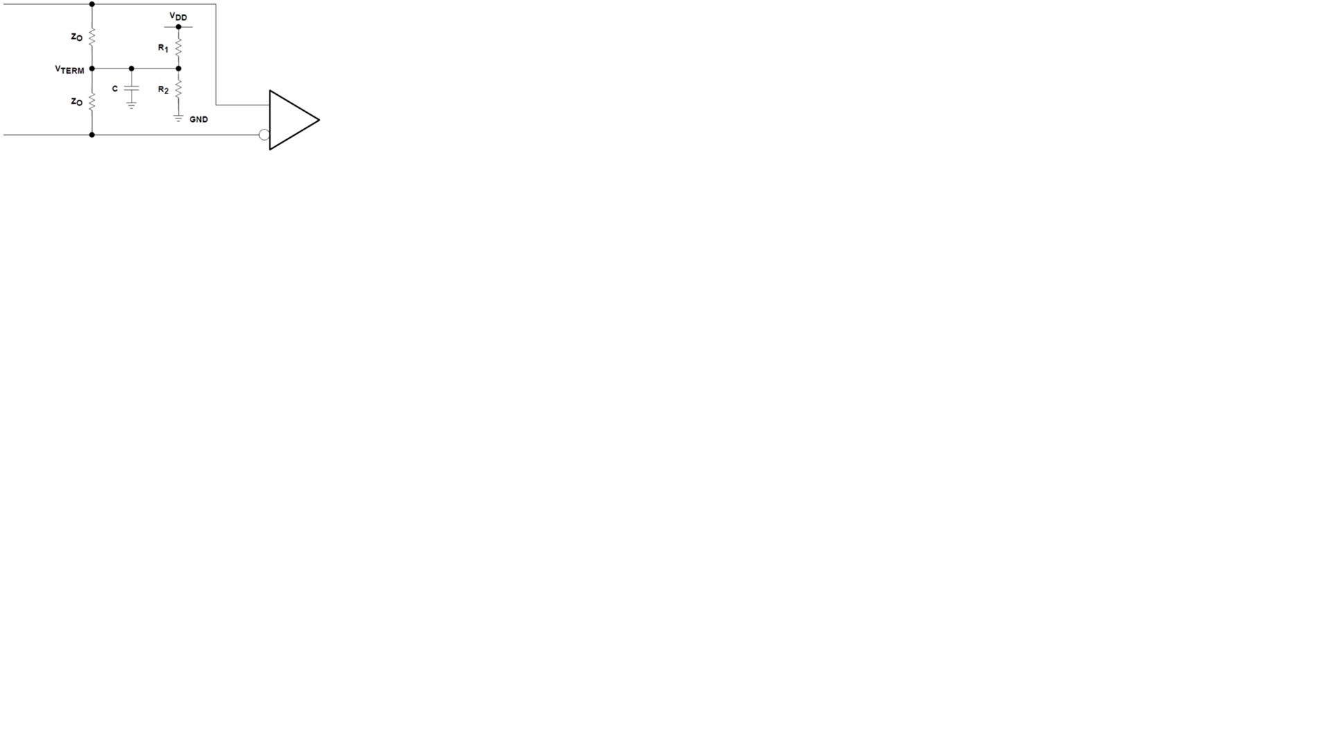
    3. This termination scheme inside the TLK2711 receiver with its additional Capacitor to minimize differential skew and common-mode noise was also recommended in one of TI app notes. Is the cap shown below also implemented inside the TLK2711-SP receiver?

    Thanks

    -Ali