This thread has been locked.

If you have a related question, please click the "Ask a related question" button in the top right corner. The newly created question will be automatically linked to this question.

PCA9306 IBIS modeling

Other Parts Discussed in Thread: PCA9306

Hi,

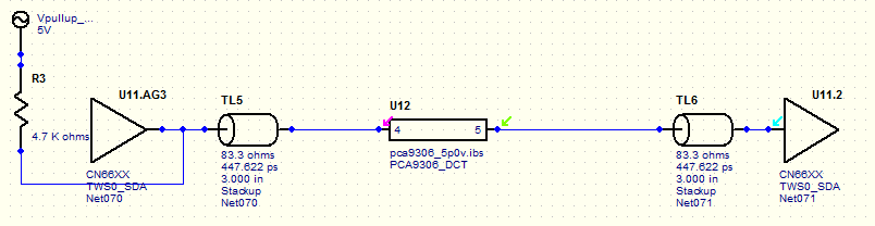
There are questions in IBIS modeling of PCA9306.

setup is as below.

4.7kohm pull up and transmission line are used because there is no test load guidance.

IBIS model is used per each VDD because [Model Selector] is not needed in case of series switch model,

Phenomenon

1. there is very little difference between max/typ/min

2. typ case and max case is almost same in case of 5V VDD

Are these phenomenon correct results?

 pca9306_2p5v.ibspca9306_3p3v.ibspca9306_5p0v.ibs

  • Hello David,

    I assume that this graph you posted shows the input at the receiving buffer with a stimulus applied at the transmitter.

    I notice is that you do not have a pull up resistor on the receiving end of the IBIS simulation setup. I believe this is contributing to the phenomenon you are viewing.

    Your pull up rail voltage (5V) is also out of device spec on the SDA1 side. The voltage on the SDA2 side must follow this relationship: VCC2 >= VCC1 + 0.6V. VCC1 (SDA1 side) has a supply range of 1.2V to 3.3V, and VCC2 (SDA2 side) has a supply range of 1.8V to 5.5V as seen in section 8.1 on page 8.