This thread has been locked.

If you have a related question, please click the "Ask a related question" button in the top right corner. The newly created question will be automatically linked to this question.

TLK2711 Clock Recovery Parameters

I need to obtain the clock recovery PLL parameters for component qualification of TI TKL2711 general purpose gigabit transceiver. These parameters are needed for the jitter measurement software in the section of clock recovery options on the oscilloscope.


It appears to me that TI Technical Support is not in operation anymore, does anyone know the required parameters? Please help.


1. Order of PLL -- first order or second order


2. Loop BW or Jitter Transfer Function BW


3. If second order, need the damping factor?

Thanks!

  • Hi David,

    Please let me check with the designers and ASAP I will provide you an answer.

    Best Regards!
    Luis Omar Morán Serna
    High Speed Interface Group
    SWAT Team
  • Hi David,

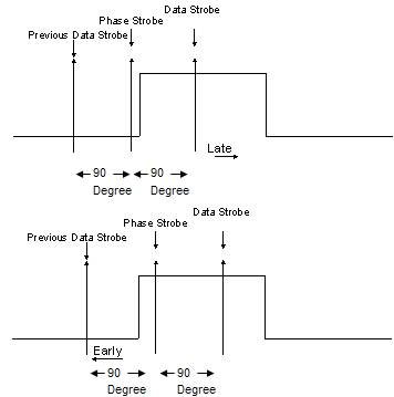
    TLK devices use a 2x oversampled CDR to dynamically adjust the sampling phase in order to track the phase of the input data stream. This clock recovery technique samples the received serial data both during the data periods (center of the eye diagram) and during the transitions. It then determines whether the current sampling point needs to be moved earlier or later by comparing the value of the transition sample to the two adjacent data samples:


    If a transition occurs and the phase sample matches the previous data sample, then the current sampling point needs to be moved later. If the phase sample matches the next data sample, then the current sampling point needs to be moved earlier. These “early/late” decisions are accumulated, and once a certain threshold is reached the update will take effect. The sampling point is adjusted by changing the clock phase that is output from the phase interpolator. Typical distances between phase steps are 1/48 or 1/64 of a bit period (unit interval).

    This kind of structure is not new – it was (to my knowledge) first described by JDH Alexander in 1975 (in “Clock Recovery from Random Binary Signals,” published in Electronics Letters). It has been used in many TI designs and has been in many RRH deployments.

    The rate at which this CDR can update to track input data phase variations is determined by
    1. The average number of bits required to generate an early/late decision (the decisions can only be made after a transition, so this is related to the signal’s transition density)
    2. The number of early/late votes that are needed for a phase update to be issued
    3. The magnitude of a phase update.

    Note that considering these three factors will give you a maximum tracking rate rather than a bandwidth (as you might have with an analog PLL-based CDR). This means that the maximum jitter frequency that can be tracked is dependent on the jitter amplitude (similar to slew rate limiting in amplifier circuits). The TLK2711 is designed to be able to track a sustained rate offset of +/- 200 ppm between the transmitted (local) and received (remote) data rates. This is due to the clock accuracy requirement of +/-100 ppm; if both sides of the link can vary by this amount, then the maximum difference is +/- 200 ppm. Note that this is the minimum rate required to support the clock accuracy specification, so the actual tracking rate should exceed this number (a typical target might be 400-500 ppm).

    The structure of the TLK2711 CDR should not introduce issues in this design. There are some concerns, though, that apply regardless of PLL structure:
    1. A reference clock signal is needed for link start-up, even on the RRH side. After start-up, the RRH clock can transition from the local clock domain to the recovered clock domain.
    2. The data output from the TLK2711 deserializer will track phase/frequency variations in the received serial data. Since the jitter cleaner bandwidth is very low, there will be some transient periods where the system clock leads or lags the deserialized data. The receiving system should implement a FIFO to help absorb these short-term variations.

    I hope this helps, if not, please let me know to find out a more accurate answer.

    Best Regards!
    Luis Omar Morán Serna
    High Speed Interface Group
    SWAT Team

  • Hi Luis,

    Thanks for the detail discussion on the interpolator and early/late clock data recovery. I try to extract the clock recovery parameters from you answer, but I still need more specific details on the design of TLK2177. Here are my questions.

    1. What is the number of transition bits required to generate an early/late decision for TLK2711?

    2. What is the number of early/late votes needed for a phase update on TLK2711?

    3. For TLK2711, is the magnitude of phase step 1/48 or 1/64 UI?

    My objective of this forum question is to obtain the clock recovery parameters needed for the TLK2711 transmitter intrinsic jitter measurement and receiver jitter tolerance verification. I use Keysight EZJIT Plus and Tektronix DPOJET software to measure the jitters. The software clock recovery methods include constant frequency, first order PLL, and second order PLL, and many other options. Here are two image of the user interface for setting the clock recovery parameters for first order and second order PLLs, taken from page 8 of the Keysight EZJIT data sheet link below.

    literature.cdn.keysight.com/.../5991-1315EN.pdf

    Please answer the following questions for TLK2711.

    1. Is the TLK2711 receiver clock recovery a first order PLL or second order PLL?
    2. Should I model it as Jitter Transfer Function (JTF) or Observed Jitter Transfer Functions (OJTF)?
    3. What is the loop bandwidth for either JTF or OJTF?
    4. If it is a second order PLL, what is the peaking or damping factor?

    Thank you.

    David

  • Hi David,

    Please let me request these values with the designers. ASAP I wil let you know the data.

    Regards!
    Luis
  • Hi David,

    Q1. What is the number of transition bits required to generate an early/late decision for TLK2711?

    A1: The cdr looks at 8ui every 32ui which equates to 8 votes (early/late/neither).  If there is a majority the phase is updated. This answers question 2 as well.

    Q2. What is the number of early/late votes needed for a phase update on TLK2711?

    A2: Refer to Q1.

    Q3. For TLK2711, is the magnitude of phase step 1/48 or 1/64 UI?

    A3: 1/64

    Q4. Is the TLK2711 receiver clock recovery a first order PLL or second order PLL?

    A4: First order

    Q5. Should I model it as Jitter Transfer Function (JTF) or Observed Jitter Transfer Functions (OJTF)?  

    A5: Not sure what the difference is.

    Q6. What is the loop bandwidth for either JTF or OJTF?  

    A6: We never actually measured it but it is effectively set by the fact that we only mode 1/64 UI every 32UI.

    Q7. If it is a second order PLL, what is the peaking or damping factor?  

    A7: Not second order.

    Please refer to this document: 

    You could extract important information from this document due to this device is similar.

    Best Regards!

    Luis Omar Morán Serna

    High Speed Interface Group

    SWAT Team