This thread has been locked.

If you have a related question, please click the "Ask a related question" button in the top right corner. The newly created question will be automatically linked to this question.

How to use TCA4311A for repeater

Other Parts Discussed in Thread: TCA4311A, TCA9517

Dear Technical Support Team,

 I have two questions about TCA4311A(I2C Hot Swappable 2-Wire Bus Buffers).

Q1.)

"Figure 13. Repeater/Bus Extender Schematic" of datasheet shows back-to-back connection of two TCA4311A.

This figure shows that SDAOUT(SCLOUT) of left side(System1) and SDAOUT(SCLOUT) of right side(System2) are connected each other(Not Input and Output connection).

Why is that connection? Is it the reason why TCA4311A has bi-directional buffer and out is card side of TCA4311A?

If you have the other reason, please let me know.

Q2.)

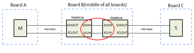
Customer's application has many boards including I2C interface and these connects in series with harness.

So they want to use TCA4311A to improve a blunt signals using connection like a " Figure 13. Repeater/Bus Extender Schematic ".

Following figure shows the simple situation for customer's system and they want to place it on middle of three boards(In fact they have more boards).

Should they use two TCA4311A and connect IN-to-IN(SDAIN and SCLIN) for main I2C side and OUT(SDAOUT and SCLOUT) is for harness side?

【datasheet】

http://www.tij.co.jp/jp/lit/ds/symlink/tca4311a.pdf

Best Regards,

y.i

  • Hello Y.I,

    The main purpose of the TCA4311a is to provide hot swap capabilities on an I2C bus. In the picture you posted (Figure 13), it shows how the TCA4311a is meant to go on the removable board at the input of the. From what you describe, it sounds more like you are looking for a repeater that can be used in series to string multiple devices together. 

    While the picture you show in your Q2 would work, I would not recommend it because the 4311A has the following property (see page 11 of the datasheet, 10.2.1.1.1 Input to Output Offset Voltage): Vlow2 = Vlow1 + 75mv + [(Vcc/R) * 100]. Where Vlow1 is the low voltage applied by a device at one side, and Vlow2 is the corresponding voltage you will get out of the other side of the device. You will experience higher VOLs are you put more of these in series, and could eventually violate your VIL of the slave devices. So depending on how many of these you are wanting to use in series, you may violate VIL.

    I would recommend looking at the TCA9517, as the device is designed to be put in series (B side to A side), see picture below from datasheet:

    Lastly, my final concern will be frequency of I2C operation. Depending on how many repeaters you are going to use, the sum of propagation delays will likely become too  large to allow for 400kHz operation. You will likely have to operate at a slower frequency, such as 100kHz. Of course this depends completely on the cables used, and how many repeaters are used.

  • Hello Jonathan,

    Thank you for your quick reply.
    I undestarnd that out side of TCA4311a provides hot swap capabilities on an I2C bus for removal board (Q1 Answer) and
    you would not recommend the picture I show in Q2 , because offset voltage buildup of TCA4311a in series (Q2 Answer).
    I would suggest TCA9517 instead of TCA4311a . My understanding is that it doesn't have voltage offset buildup in series,
    because datasheet Page.2 says following . Is this correct?

    ■Datasheet Page.2
    Multiple TCA9517s can be connected in series, A side to B side, with no buildup in offset voltage and
    with only time-of-flight delays to consider.

    Best Regards,
    y.i
  • Y.i,

    You are absolutely correct. The TCA4311a will have a static voltage offset build up when placed in series, but the TCA9517 will NOT have the voltage offset build up.

    You must be sure that the A side connects to the B side, otherwise the signal will not propagate through.