This thread has been locked.

If you have a related question, please click the "Ask a related question" button in the top right corner. The newly created question will be automatically linked to this question.

DS110DF111 set register for Eye Mask Hit Ratio test

Other Parts Discussed in Thread: DS110DF111

Hi all,

My board is using DS110DF111 retimer at data rate 10.3125Gbps(SFP+). I use TekExpress Scope DSA71604C to measure Eye Pattern.

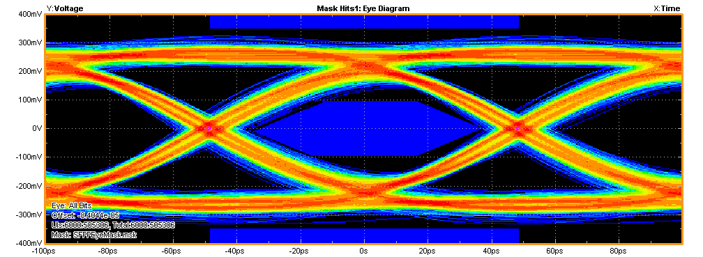
1. When running with default value of DS110DF111(power on value), the Eye diagram as below:

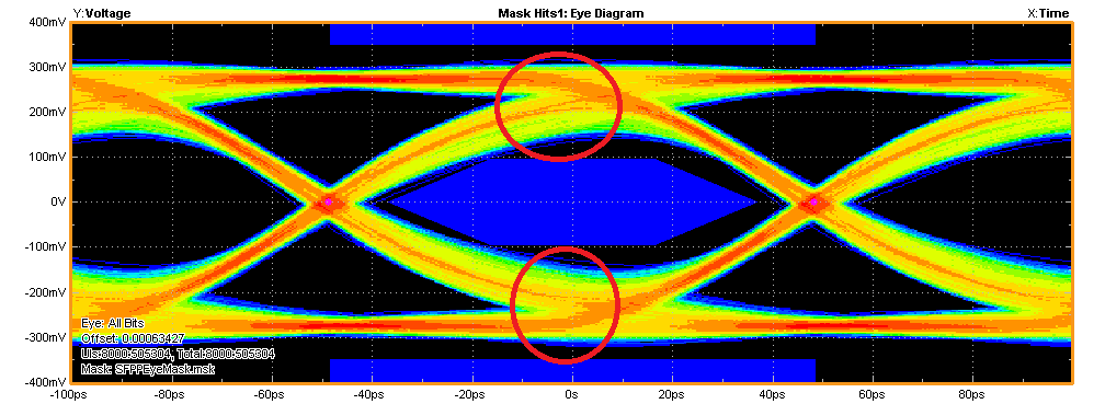
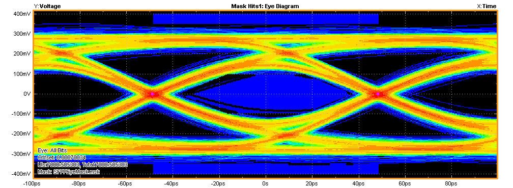
2. After I change Rate/Subrate, Driver De-emphasis, Output Driver VOD, Eye Diagram looks better, but still not good:

Here is registers I set for channel A of retimer:

0000: 00 00 dc 00 00 00 00 00
0008: 00 00 10 0f 08 00 93 69
0010: 3a 20 a0 90 00 02 7a 25
0018: 40 23 00 03 24 00 e1 55
0020: 00 00 00 40 03 00 01 00
0028: 84 40 30 00 72 84 00 c6
0030: 00 40 11 88 bf 1f 33 00
0038: 10 00 a5 33 8e 00 80 00
0040: 00 40 80 50 c0 90 54 a0
0048: b0 95 69 d5 99 a5 e6 f9
0050: 00 00 00 00 80 00 00 00
0058: b0 95 69 d5 99 a5 e6 f9
0060: 00 00 00 00 00 00 00 00
0068: 00 0a 44 40 00 00 00 00
0070: 03 04 10 10 10 10 00 00
0078: b0 95 69 d5 99 a5 e6 f9
0080: 00 40 80 50 c0 90 54 a0
0088: b0 95 69 d5 99 a5 e6 f9
0090: 00 00 00 00 80 00 00 00
0098: b0 95 69 d5 99 a5 e6 f9
00a0: 00 40 80 50 c0 90 54 a0
00a8: b0 95 69 d5 99 a5 e6 f9
00b0: 00 00 00 00 80 00 00 00
00b8: b0 95 69 d5 99 a5 e6 f9
00c0: 00 40 80 50 c0 90 54 a0
00c8: b0 95 69 d5 99 a5 e6 f9
00d0: 00 00 00 00 80 00 00 00
00d8: b0 95 69 d5 99 a5 e6 f9
00e0: 00 40 80 50 c0 90 54 a0
00e8: b0 95 69 d5 99 a5 e6 f9
00f0: 00 00 00 00 80 00 00 00
00f8: b0 95 69 d5 99 a5 e6 04

Would you please help in this case, which registers need to be modified to make the Eye better?

Thanks,

Pha

  • Hi Pha,

    There is enough loss between the DF111 output and your measurement point to require more De-emphasis.  When more de-emphasis is added, the VOD level needs to be increased to maintain the eye height.  I added 10 inches of FR4 to the output of the DF111.  This produce very similar waveforms to your result.

    The waveform above uses your register settings for DE = -3.5dB and VOD=1000mV

    Changing the DF111 settings to DE = -5.6 dB and VOD = 1200mV produces a cleaner waveform.

    I am not sure why you had to change the rate/subrate.  I just wanted to start with the waveform quality first.  The new DE setting is register 0x15 = 47'h. The new VOD setting is register 0x2D = 86'h.

    Regards.

    Lee

  • Hi Lee,

    Thank you for your help. I increase Output VOD = 1200 mV and De-emphasis = -6.0dB, eye looks better:

    The eye mask test pass but margin is so small. If  add more de-emphasis,  eye is worse. Would you please tell me which registers I need to modify to make eye cleaner?

    Because my board only uses 10.3125 so I tried change Rate=0b11 and Subrate=0b00

    Thanks,

    Pha.

  • Hi Pha,

    I will take some additional trial and error since my channel is different than your system.  The loss in the system is quite a lot for SFP+, but I think we may be able to make some small improvements.  You will have to try various combinations of DE, VOD, and edge rate.  These are the only 3 adjustments we can make.

    The -6.0 DE is a little too much with the fast edge rate (see diamond shape at crossing) .  It may work better with -5.6dB setting in register 0x15. 

    I would try to increase VOD to 1300mV and/or change to a slower edge rate.  The edge rate can be slowed down slightly by writing register 0x18[2] = 1'b.  This make cut down on the reflections in your channel and decrease the Dj slightly.

    Regards,

    Lee

  • Thanks Lee,

    I tried but it didn't improve more.

    Should I need to change CTLE settings and DFE taps? 

    Regards,

    Pha.

  • Hi Lee and all,

    DS110DF111 has PRBS9/31 generator.  When output mode is data output of the internal PRBS signal generator, does this PRBS9/31 is better than Retimed-data?

    1) If PRBS9 from PRBS signal generator doesn't pass 'Data Dependent Jitter' test with any various combinations of DE, VOD, and edge rate, then can Retimed-data pass?

    2) If PRBS31 from PRBS signal generator doesn't pass 'Eye Mask Hit Ratio' test with any various combinations of DE, VOD, and edge rate, then can Retimed-data pass?

    Thanks,

    Pha.

  • Pha,

    Please see ansers inline.

    DS110DF111 has PRBS9/31 generator.  When output mode is data output of the internal PRBS signal generator, does this PRBS9/31 is better than Retimed-data?

    A: There are two ways to generate a PRBS pattern with the DS110DF111. One way uses the internal VCO in a free-running state.  The other uses the input signal to set the VCO frequency.  In either case the PRBS pattern will not improve the Retimed data eye opening.

    1) If PRBS9 from PRBS signal generator doesn't pass 'Data Dependent Jitter' test with any various combinations of DE, VOD, and edge rate, then can Retimed-data pass?

    A: If the PRBS pattern is using the input data to set the VCO frequency then PRBS data and retimed data are exactly the same.  Only the output controls DE, VOD, and edge rate will change the eye opening. 

    2) If PRBS31 from PRBS signal generator doesn't pass 'Eye Mask Hit Ratio' test with any various combinations of DE, VOD, and edge rate, then can Retimed-data pass?

    A: Same as #1.

    Because of the amount of loss between the DS110DF111 and the host connector the eye will be marginal.  There is just enough DE to manage the eye mask at the limit when the channel is very clean.  There is a slight distrubance in your system channel at this point I think we are out of adjustments beyond the waveform which exhibits a "marginal" pass.   

    Regards,  Lee

  • Thanks Lee,

    About answer 1,

    Lee Sledjeski said:

    1) If PRBS9 from PRBS signal generator doesn't pass 'Data Dependent Jitter' test with any various combinations of DE, VOD, and edge rate, then can Retimed-data pass?

    A: If the PRBS pattern is using the input data to set the VCO frequency then PRBS data and retimed data are exactly the same.  Only the output controls DE, VOD, and edge rate will change the eye opening. 

    How about PRBS pattern using the internal VCO in a free-running state?

    I think if the input data of DS110DF111 is not good, may output is also not good. So I would like to know which is the best signal from output of DS110DF111 to the connector on my system: Raw, Retimed or internal PRBS?.

    Regards,

    Pha.

  • Hi Pha,

    How about PRBS pattern using the internal VCO in a free-running state?

    A: In a free running state you will not have precise control over the output datarate.  It will not stay at a constant value, it will "wander" up and down.

    If the input is not good what is the best output Raw, Retimed, or internal PRBS?

    A:  As long as the input signal is good enough to lock, the Retimed or Internal PRBS (using the input signal for VCO control) will be the best.  Raw data will never be the best option.

    Regards,

    Lee

  • Hi Lee,

    Thank you so much for your help.

    Regards,

    Pha

  • Hi Lee and all,

    I have others questions, please help:

    1. My board has another 10.3125 Gbps port. I tuned the DE, VOD and edge rate. Below is one of the best Eye(pass Jitter test but fail Eye Mask Hit Ratio test):

    Would you please help how to make the signal at the red area  thinner? 

    2. I measured output of DS110DF111 (at connectors), its shape looks below:

    Would you please tell me which registers of DS110DF111 control the Va, Vc and Vd in above picture individual?

    Thanks,

    Pha.

  • pha said:

    Hi Lee and all,

    I have others questions, please help:

    1. My board has another 10.3125 Gbps port. I tuned the DE, VOD and edge rate. Below is one of the best Eye(pass Jitter test but fail Eye Mask Hit Ratio test):

    Would you please help how to make the signal at the red area  thinner? 

    2. I measured output of DS110DF111 (at connectors), its shape looks below:

    Would you please tell me which registers of DS110DF111 control the Va, Vc and Vd in above picture individual?

    Thanks,

    Pha.

    Hi all,

    I would greatly appreciate any help.

    Thanks,

    Pha

  • Pha,

    The wider area circled in red is due to some type of channel discontinuity.  In order to move the waveform away from the center eye mask area you will have to increase VOD and DEM.  The VOD and DEM controls work together to define the Va and Vb portions of the waveform in your post.  There is no control for Vc adjustment. 

    Moving the waveform away from the center eye area will likely result in some marginal hits in the outer eye mask areas.  With the current channel between the DS110DF111 Tx and the scope it may not be possible to meet all jitter and eye mask constraints.  I would use a slight increase in VOD and DEM to ensure no hits to the eye mask center.

    Regards,

    Lee

  • Hi Lee,

    Thank you so much for you help.

    Best regards,

    Pha