This thread has been locked.

If you have a related question, please click the "Ask a related question" button in the top right corner. The newly created question will be automatically linked to this question.

TLK110 Does not negotiate

Other Parts Discussed in Thread: TLK110, TLK100

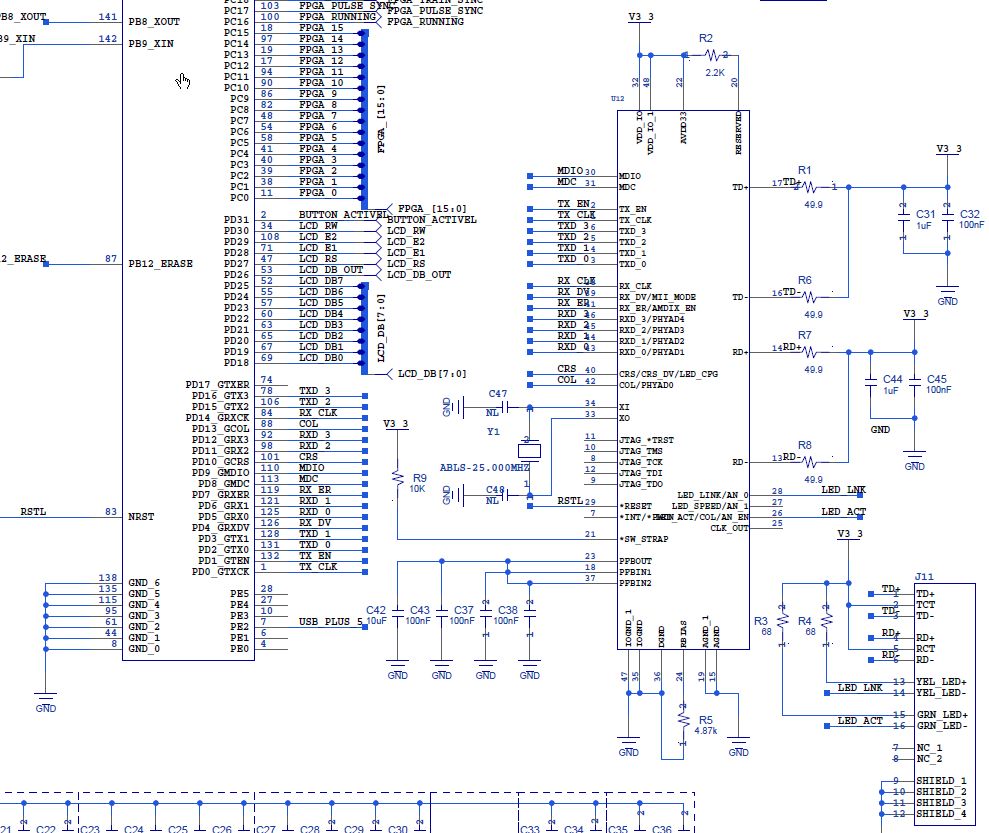
I have a board with the TLK110 wired as per the attached schematic.  (The circuit on the left is an ATMEL ATSAM4E)  J11 contains magnetics as well as the connector.  

The problem is that it does not negotiate or establish a link. when a cable is connected from J11 to either the Ethernet connector on my PC or a router.   Some other observations:

1. None of the LED's on the connector/ magnetics go on

2. There is 3.3 V on pin 48.  It's power-on rise-time is ~ 2ms

3. There is 1.5 V on PFBOUT 

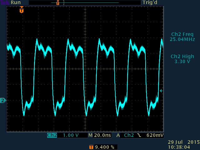
4. There is 25 MHz oscillations on X1 and clock out

5. The RESET pin is connected to a normally open switch to ground.  It sits at 3.3 V until the button is depressed when it goes to ground and then returns to 3.3V if the button is released.  Doing this doesn't seem to effect the TL!K!10.  It's as if it is continually in reset. 

6 On the off-chance that the chip was defective or damaged, I replaced it and nothing changed. 

  • Hi Seth,

    Your schematic looks ok but I have a few questions.  Is R5 a 1% resistor?  What voltage do you see at pin 24?

    I see a large bank of caps just outside of the shot.  Are these decoupling for the supply pins?

    Could you give me a dump of your registers during operation to get a better idea of what is happening with your PHY?

    Best Regards,

  • Thanks for your quick response.

    R5 is a 1% resistor

    The voltage at pin 24 is 0 volts (nada). This does not seem good.

    Yes, these are decoupling caps for the TLK110 and other. There are 4 caps (10 uf, 10 nf, 1nf, and 100 pf) for each of the 3 power pins 22, 32,48. On second look, perhaps they could be closer to the respective pins, but I don't think this is my issue right now.

    Unfortunately, the firmware is not operational with regard to the phy at this time so I can't give you a register dump. I am debugging with sample code from Atmel for the LWip and the plan was to get the hardware working , then this sample code, then the real code. But I am stuck on phase 1, getting the hardware. working.

    Furthermore, it was my understanding that the TLK110 would work without any firmware, that the power-up default values were pretty much the standard operating parameters, and that unless you want something special, you didn't have to program the chip at all. Is this not correct?
  • Hi Seth,

    You are correct about the TLK110 coming up without external firmware. That is the purpose of the straps to allow you to configure common settings without a management bus.

    The register dump would however help to make sure things are going well and that something weird isn't happening like your PHY staying in reset or disabling auto-negotiation.

    Pin 24 should be 1.215V+/-5%. Seeing 0V worries me. Without MDIO access however, it is hard to tell if the PHY is alive or not besides scoping the TD/RD pin pairs.

    The load caps on your schematic say NL. Are these installed and what values are they?

    Best Regards,
  • Hi Rob,

    It took a bit of doing to get the register dump and I hope it is correct.

    And the answer is ....
    0x00 for every register 0 to 0x171 in every phy address 0-7. That's a total of 2960 reads.

    It looks like the phy is a lump of sand., except that the Clock-Out is running with a 25 MHz clock and the 1.55 voltage is correct.

    It still seems that the 0 volts on Pin 24 is a big clue. But I don't know where to go from here. I have checked the schematic pin out with the TLK data sheet and all is well there.

    I don't know what you mean by the "load caps" on the schematic saying NL. The only NL caps that I see are C47 and C49 around the crystal and they are, in fact, not loaded, but the oscillator is clicking along.

    I have noticed something not quite right. R3 and R4, the pull-up for the LED's, are 68 ohms. This means that current through the LEDs and into the TLK pins 25 and 28 will be 16 ma. This is more than the specified 4 ma output drive of the TLK. So I am not totally relying on the LED's to tell me what is happening. But do you think this could screw everything up?
  • Hi Seth,

    Yes I was talking about the load caps for your crystal. Depending on the manufacturers recommendation, you'll need some load capacitance so that you don't violate our frequency and PPM spec.

    Please add caps of the value that the manufacturer of that crystal specifies.

    Also add a 2.2k pull-up to the MDIO line. Do those two things and then read the PHY registers again. I suspect with the crystal properly loaded, your digital core will come up and read out something.

    In regards to the LED current limiting resistors, choose a value to keep your current in the range of 4-5 mA. 16mA shouldn't cause the part to be immediately damaged, but long term it may cause LED driver failures in the part. I don't think this is the source of your current problem.

    Best Regards,
  • I have added a pull-up on the MDIO line as you suggested.

    I have not added caps to the crystal because its physically challenging on the proto-type where there is no layout location for them. I believe these capacitors are unnecessary to get things going, but I will add them in the next build of the board. I believe they are unnecessary because the oscillator is working as demonstrated by the presence of a good 25 MHz symmetrical square wave on the clock_out pin (pin 25). (3,3V amplitude, 57% duty cycle, 25.00 MHz frequency)

    The clock and the 1.55 voltage supply are the only things working. I still have no indication of negotiation and all the register read-backs show 0x0000. What else can you suggest?
  • Are you still there?

    I am still having the problem. This is what I have done over the weekend.

    I looked at the layout and verified that it corresponds to the schematic.

    I have looked at every one of the 48 pins . They all see normal except for the bias which is 0 volts and you have indicated that it should be 1.2V
    TXCLK and RXCLK alternated between 2.5 MHz and 25 MHx. TD+ and TD- and RD+ and Rd- have 6 to 3 volt pulse trains with quite periods in the middle. It seems like the TLK110 is trying to negotiate but can't get good data from the other side.

    I am thinking that the chip is damaged and the major symptom is the lack of bias voltage which prevents the read recovery circuits from working properly. But I have already replaced the chip once and it's not an easy thing to do and I don't want to do it again on a hunch. So the question is how did the bias circuit get damaged. At various times, the 1.5 volts was disconnected and the crystal removed with the power on. Could either of these conditions damaged the chip? Also the pull-ups on the LED_ACT and LED_LINK pins are way to small (too powerful). Could that be the culprit?

    Bottom line: should I replace the chip?
  • FINALLY GOT A GOOD REGISTER DUMP

    I found a mistake in the code to get the TLK's register dump.  (I was not enabling  gmac management.  Who knew?)

    Anyway here it is  in the attachment.  I hope you can give me some insight from this.  My take is that the receive circuitry is not working.  Is this consistent with the bias pin at 0?

  • Hi Seth,

    It looks like you read out 0x3900 for BMCR(0x0) register. Can you verify this? Bit11 is set which is IEEE power down mode. Your PHY shouldn't be doing anything at all except giving you register access. Change bit11 to 0, default BMCR should be 0x3100.

    The pulse train you are looking at is the auto-negotiation process. This might be reflected from the link partner trying to link with the PHY. I see you have an aneg error as you pointed out. Was this with a link partner connected? Or with the TD/RD pins terminated?

    How long is the cable connecting the link partner?

    At this point I dont suspect that the part is damaged. My biggest concern still is the lack of load capacitance on the crystal. You may want to consider which is easier to perform, adding capacitance to the crystal(VERY highly recommended) or replacing the part.
  • Seth,

    Could you also send over scope shots of your crystal oscillating? Also are you getting tx_clk from the MAC to the PHY?

    When you mentioned seeing a pulse train, did you have a far end link partner connected to the PHY? Or was this with the PHY lines terminated?

    Best Regards,
  • Hi Rob,

    I've made a little progress, I think.  I found that the bias resistor that connects RBIAS, pin 24, to ground was 4.87 ohms,  not 4.87 K ohms.  (It was 1000 times too small.)  For a moment, I thought that this was the problem.  Alas,no.  After replacing the resistor (with a 4.99K in parallel with 200K, It's all I have),  I found that pin 24 was now 1.24 volts as you indicated that it should be.)  But I still am not getting communication with my p.c.  

    The first dump after power turned on, I had 0x3100 in the BMCR as you indicated that I should (See attached screen dump)

    Previously, the pc would indicate no connection and nothing more would happen.  Now it continually tries in that  X that used just sit there, now disappears to be replaced by the "waiting" ring, to again return to the X.  

    After I tried that again, it returned to the original 0x3900 in the BMCR, but the pc bahavior continued to be different.

    To answer your questions.  pin 25, clock_out is shown below.  It is 25 MHz 

    With regard to see a pulse train, I believe I saw it both with and without the partner.

    By the way the partner is a a p.c. with the IP4 set to a fixed adress.  I have tried it with the LInk-layer Topology Responder and Discovery Mapper both enable and disabled with the same effect.

  • To answer your question about TX_CLK. Yes measuring at both the MAC and PHY I see a 25 MHz square wave alternating with a 2.5 MHz one as long as the Ethernet cable is connected to the p.c. When it is disconnected I see only the 2.5 Mhz
  • Hi Rob,

    Haven't heard from you in a while. Are you still with me?

    Some more info. It turns out that if you continually read the BMCR it reports mostly 0x3900 but there are random reads when 0x3100 is reported, about 1 in 5 times are the average, but this is variable. It looks to me like the TLK100 is negotiating successfully, but then something causes it to start a new negotiation.

    I removed the 68 ohm pull-ups from the LED_ACT and LED_LINK pins on the off chance the fact that they are too small has some strange deleterious effect. No joy. It works exactly the same.
  • Hi Seth,

    I am glad to see you are getting progress on the board. The bit that is toggling is IEEE power down which is a sleep mode defined for all 802.3 compliant PHYs. This is a strange occurence. I still believe we need to square away your clock before we can look at all the data without having doubts about validity of that data.

    Your scope is reporting the frequency is 25.04 MHz but that actually violates our PPM spec which is +/- 50 ppm. +/- 50 ppm is 25.0125 MHz.

    Best Regards,