This thread has been locked.

If you have a related question, please click the "Ask a related question" button in the top right corner. The newly created question will be automatically linked to this question.

TPS65982 / Power Delivery without connecting D+/D- signals

Guru 29690 points
Other Parts Discussed in Thread: TPS65982, TPS65982-EVM, HD3SS460EVM-SRC, HD3SS460

Hi Team,

My customer is evaluating two TPS65982 EVMs.
He set ID#6 for provider and ID#7 for consumer, then connect these EVMs with typeC cable.


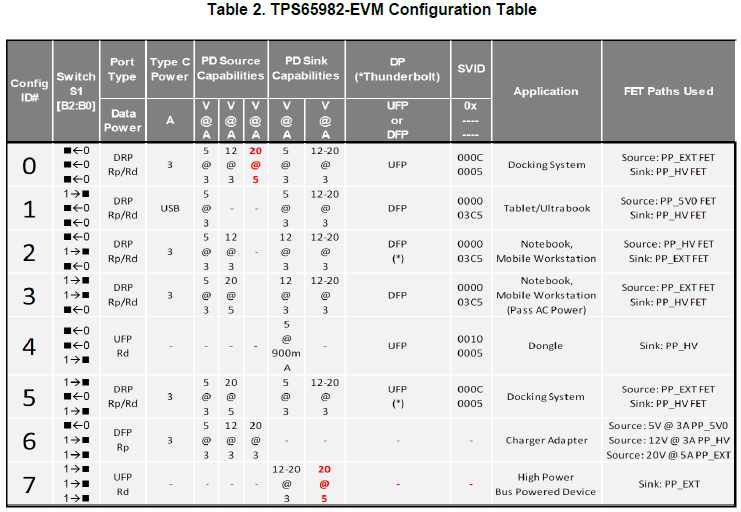
Is it possible to confirm the function of Power Delivery without connecting D+/D- signals?
(It seems my customer couldn't confirm the PD function under above condition.)
This usage may be not normal case but he would like to achieve it for just test(demo) use.

Best Regards,
Yaita / Japan disty

  • Moving to the correct forum.
  • May I have your comment?

    Best Regards,
    Yaita

  • Yaita,

    D+/D- pins are not required for USB Type-C detection or USB PD communication at all.

    All features of the EVMs will work even if D+/D- were not available.

    There isn't even a way to test D+/D- easily on the EVMs, because the other end of the USB2.0 Mux (USB_RP_P and USB_RP_N) is routed to a header and not connected to an IC on the board.

  • Hi Brian-san,

    Does it mean there is no effect on PD function for TPS65982EVM if C_USB_BP/N and C_USB_TP/N are all open?
    I heard my customer couldn't confirm PD function...so I would like to confirm just in case.

    Best Regards,
    Yaita

  • Yes, I guarantee PD functionality will work if C_USB_BP/N and C_USB_TP/N are not connected to the Type-C connector.

    If you order 2 TPS65982-EVM boards from the TI Store, then you can connect jumper wires from CC1 (or CC2) on one EVM to CC1 (or CC2) on another EVM and verify that PD communication occurs.

    If you also connect a jumper wire from VBUS on one EVM to VBUS on the other EVM, you will see that they can power each other also.

    The LEDs will light up appropriately and there are easy-to-access Test Points on CC1, CC2, and VBUS.

  • Hi Brian-san,

    I got 2 TPS65982EVM boards and tried the following as you said, however I couldn't see normal PD function.
    On the other hand, PD function is no ploblem when connecting Type-C connector between EVMs.
    -------------------------------------------------------
    >connect jumper wires from CC1 (or CC2) on one EVM to CC1 (or CC2) on another EVM
    >connect a jumper wire from VBUS on one EVM to VBUS on the other EVM
    -------------------------------------------------------
    Could you try the same evaluation to confirm it?

    I used the following TPS65982EVMs.
    - Provider (ID#6):TPS65982EVM (rev.D, 9.00)
    - Consumer (ID#7):TPS65982EVM (rev.C, 8.07)

    Your support would be really appreciated.

    Best regards,
    Yaita

  • Yaita-san,

    Yes, I have already done this test when I was evaluating the HD3SS460EVM-SRC and HD3SS460EVM-SNK with the TPS65982-EVM:
    The HD3SS460 EVMs were connected with the Type-C cable and I had to connect CC1 and CC2 from the HD3SS460 to the TPS65982-EVM with jumper wires. I connected VBUS with jumper wires also to provide power from one TPS65982-EVM to the other.

    Please measure the CC pin voltage when you are doing the test.
    CC1 on Board A (Provider, ID#6) should be pulled up to 3.3V to indicate it has an Rp pull-up current source.
    CC1 on Board B (Consumer, ID#7) should be pulled down to GND to indicate it has an Rd pull-down resistor.
    When you connect the 2 boards, CC1 should go to a mid-rail voltage (~1.67V) and PD communication should be superimposed on the DC voltage.

    Why aren't you using 2 Rev. D EVMs? It shouldn't matter, but Rev. C was not released to the web and most customers would not have a Rev. C EVM available.

    And make sure you power cycle the EVM or press the RESET button after you configure the DIP switches.

    If you are still having issues, please use an oscilloscope to measure the CC voltages while you are doing the test.
  • Hi Brian-san,

    I apologize I forgot to put pull-down resistor on CC2 pin(VCONN) for "cable orientation detect".
    I put 1kΩ pull-down resistor on CC2 for both EVMs and connect each CC1 and VBUS(and GND), then I could confirm PD function.

    I understood it is possible to confirm PD function without connecting D+/D-.
    I greatly appreciate for your support!

    Best Regards,
    Yaita