This thread has been locked.

If you have a related question, please click the "Ask a related question" button in the top right corner. The newly created question will be automatically linked to this question.

Issue with I2C bus which uses TXS0102 as Level shifter

Other Parts Discussed in Thread: TXS0102

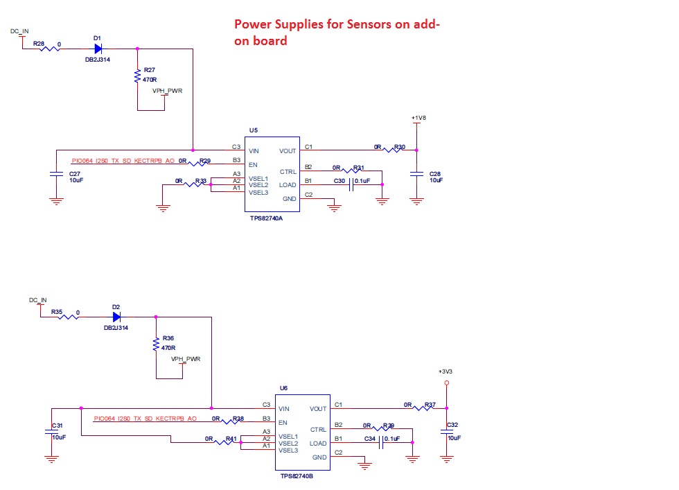
We have designed our circuit as per the attached diagram. We have a processor on which a MIPS processor is interfaced with RTC device. As the processor I2C bus is operating on 1.8V supply we used a open drain level shifter from Texas Instruments TXS0102 to translate to 3.3V voltage level which is needed by AB-RTCMC-32768KHz-EOZ9-S3 RTC device rom Abracon.Supply for this RTC is derived in this board it self.As per the data sheet given for TI level shifter pull ups are already available internal to the device which is of 10K but provision was given for external Pull-up resistors as well. We have a separate connectivity board on which we have few sensors on the same I2C bus but supply to these sensors are derived on the connectivity board itself.Provision was given at single device for 4.7K pull up resistors. Our issue is whenever we access RTC through I2C then all other sensors data is corrupting and they are misbehaving and even RTC is not working properly. Without accessing RTC other devices are accessed perfectly. I have attached all the devices which are on the I2C bus and also shown the pullups in the document. I tried removing and adding pull ups at different places but that doesn't work. Please do suggest me what might be the issue. 

I tried removing and adding pull ups at different places but that doesn't work.

Thank You.

Regards

SrikanthOur Circuit design.pdf

  • Hello Skrikanth,

    Thanks for the question, I'll be happy to help you solve this issue.

    Would you be able to supply more detailed schematics of the TXS0102? I'd like to see which side the MIPS processor is connected to and which rails VCCA and VCCB are connected to.

    Looking at the block diagram you provided, I don't see any obvious issues, so we will need to dig a little bit deeper. Allow me to ask you a few questions:

    1) What clock rate are you opperating at?
    2) Is the bus long? IE are the traces/cables to communicate on I2C fairly long ( > 1m)?
    3) Could you provide a scope shot of the SDA and SCL channel during a failed transaction, where you are seeing data get corrupted? Normally a scope picture is worth a thousand words when helping debug I2C lines
  • Hello Jonathan,

    Thank you for your reply on this.

    attached are the schematic circuits of TXS0102 and also the addon board where Sensors are present along with their power supply circuits. 

    I will provide the oscilloscope snapshots soon.

    1) We are operating the I2C clock at 400KHz

    2) Our board size is around 15 x 25 milli meters long so bus length is few millimeters. 

    Thanks

    Srikanth

  • <Duplicate Post>

  • <Duplicate Post>

  • Srikanth,

    Thanks for the post.

    Looking at your schematics, I do not see any obvious problems.

    I think a scope shot would be the best approach at narrowing down what is going on here. Preferably, if you can obtain a scope shot on the 1.8V SDA/SCL line and a scope shot (if you have 4 channels, then at the same time would be best) of the 3.3V side, so that I may see the signal propagation through the TXS0102 device.
  • Hello Jonathan,

    I just forgot to mention an issue which we found in the level translator circuit. I am posting document contains both circuits. 1st one with a design error and 2nd one with corrected circuit. Please suggest if any issue with pull ups or any other.

    Thanks

    SrikanthI2C corrected and original circuits.pdf

  • Srikanth,

    Good catch with the B1 and A2 pins being flipped.

    In regards to removing R529 and R530, You can do this because of the internal 10k pull-ups on the bus lines. Since this is the ONLY slave connected to the B side of the TXS0102, you should be ok without external pull-up resistors on that bus.

    I would keep R536 and R537 because you have many slave devices, and 10k alone may be too high. But since the TXS0102 has 10k internal pull-ups in parallel with the external 10k pull-ups, you have an equivalent pull-up resistance of 5k ohms, which should be ok for your bus.