This thread has been locked.

If you have a related question, please click the "Ask a related question" button in the top right corner. The newly created question will be automatically linked to this question.

TCA9543A not sending ACK when Programming Register in Write Mode

Other Parts Discussed in Thread: TCA9543A

Hi,

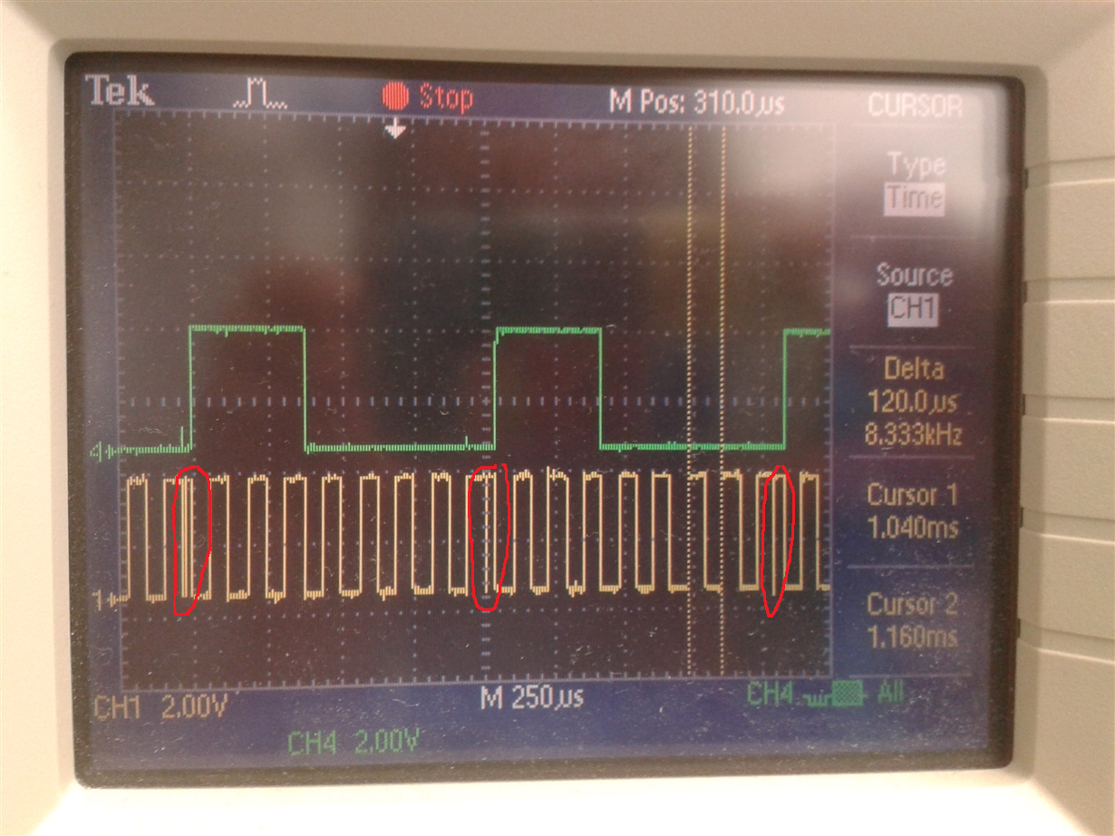
When I try to READ Control Register I receive an ACK from slave and after Control Register Value.

When I try to WRITE in Control Register the ACK is not received.

For my case A0=A1 = 0, then:

Byte to  Write Control Register: 0xE0

Byte to Read Control Register:  0xE1

What could be wrong?

Thank you

  • Hello Amaia,

    Thanks for the question.

    It does appear that you are addressing the device correctly for both read and write conditions. I think it would be helpful to obtain an oscilloscope shot of the write to the control register that fails. A scope shot can provide a lot of information in some cases.

    Do you have a schematic showing the setup of the hardware as well? Specifically, I'd like to see the pull-up resistors, any voltage translators between the master and switch, and anything else that is related to the switch.

  • Hi Jonathan,
    Thank you for your answer.


    I have pull ups in SDA,SCL,INT (master side)connected to 3,3 V and also in SDx,SCx,INTx (slaves side) connected to 1,8V. Each R = 10K

    In Channel 0 and Channel 1 there is no slave connected yet (I am developping just I2C Configuration). Could this be the problem?
    Thank you!
  • If you have pull-up resistors on all of the SDx,SCx, and INTx slave side lines, then a lack of slave devices is unlikely to be the culprit here.

    What do you have VCC connected to on the TCA9543A? It should be connected to the 1.8V bus. With these switches, VCC should be at the lowest voltage of any of the I2C devices connected to it.

    Do you have the ability to grab an oscilloscope shot during the write procedure? Preferably showing the entire transaction so that I can actually read the data being sent.
  • Hallo ,

    Thank you.

    In my case VCC = 3.3 V

    I attach the osci snapshot. 

    Master  sends 0xE0 (Write). Is the resolution OK? Tank you!

  • Thanks for the scope shot. It does not contain the start bit so i do not know where the data starts, but I see something of greater concern, which I believe the issue is caused by.

    You have small pulses on the clock line which are getting interpreted as an extra clock pulse. I am fairly sure that these glitches make the TCA device latch in an extra bit, which is making it see the incorrect address. Please see the parts circled in red in the scope shot below:

    This is a result of your I2C master. You need to figure out the cause of these glitches and get rid of them. The I2C spec mandates that all I2C devices have an internal  deglitch filter of 2us to prevent false triggers like this. But your glitches appear to be much much longer than 2us to show up on this time scale, which is why the slave device interprets it as another clock rising edge.