This thread has been locked.

If you have a related question, please click the "Ask a related question" button in the top right corner. The newly created question will be automatically linked to this question.

Pull-up resistor for PCA9306 on 5V side

Other Parts Discussed in Thread: PCA9306

Please consult. Level converter between atmega328 5V-PCA9306-bosh bmp180 3,3v w / pull-up resistor 4,7k (recomended 2,2-10K) to VREF1. My question - is there a need to put pull-up resistors in the 5V on VREF2 side and a nominal?
Thank you.

  • Hello Gennady,

    Thank you for your question!

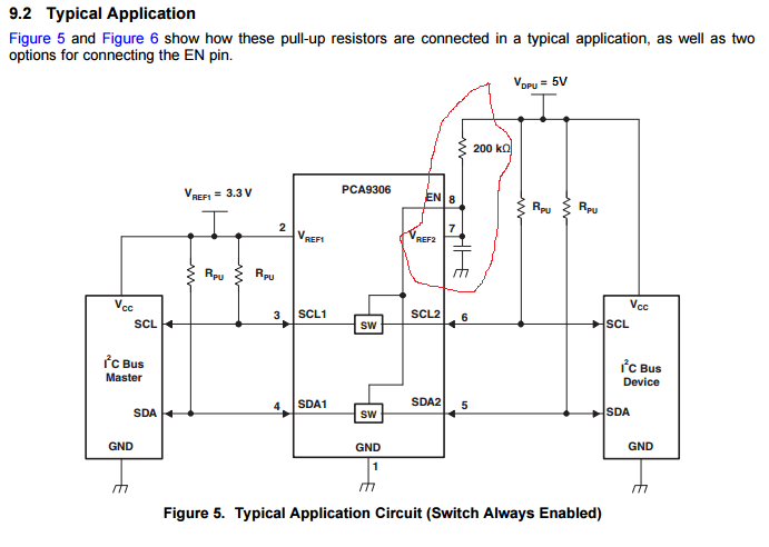
    You are correct, that you will need a pull-up resistor on the SDA/ and SCL lines to their respective power rails. This is true for both sides of the PCA9306. So both your 3.3V and 5V sides will require pull-up resistor.

    Please see the schematic below from the datasheet that I have modified to match your power supplies. Note the configuration of the part circled in red. It is very important that you wire it up that way for proper translation.

  • Hi!

    I understud about 200K and cap. I will put C=1000pF.
    About nominal of pull -up R. I planing use 4,7k on 5v and on 3,3v sides. Is it correct nominal for 5V side?
    PLS note, that MPU Atmega have push-pull standart CMOS outputs.
    Thanks!
  • Hello Gennady,

    Using a 4.7k should be fine to use on both sides.

    Keep in mind that whenever a slave or master transmits a 0, it must sink the combined current of both channels.

    For example, if you use the 4.7k pullup resistors on both sides, then the total current the slave must be able to handle is
    3.3/4.7k + 5/4.7k = 1.76 mA
  • BMP180 have SDA sink current @ VDDIO = 1.62V, VOL = 0.3V is 9 mA. But minimum pullup resistors is 2,2k. It mean 3,6v-0,3v/2,2k=1,5ma only.

    maybe (3.3-0,3)/4.7k + (5-0,3)/4.7k = 1.63mA more correct.

    Thanks!
  • Gennady,

    Your equation is more accurate. I tend to assume a VOL of 0V because it gives a little extra head room.
  • Hi!

     In page 11 of  SCPS113K –OCTOBER 2004–REVISED OCTOBER 2014 pdf for PCA I was read:

    "The I2C bus master output can be push-pull or open-drain (pull-up resistors may be required)"

    I understud-if master output  is push-pull -no resistor is needed. From this point I was start my question. Also in APM ardupilot board v2.52 resistor used only on 3,3v I2C side. From 5V side (Atmega 2560) no resistors!

    Thanks!

  • Hello Gennady,

    This is correct. If a master output is push-pull, then no pull-up resistor is necessary. The voltage translator suggested technically can translate from push-pull to open drain, but this does not mean your I2C communication will work as expected.

    What I am saying is that push-pull and I2C cannot work without some software tricks. I2C relies on its open drain property in order to send bi-directional data on a single bus line (ACK signal for example). If you do not put your master's output drivers into Hi-Z during the ACK pulse or during a read cycle, your master will be unable to read any acknowledges or data from the slave, because the master will be asserting a high or a low onto the bus line always.

    Does this make sense? You would have to make your SDA output drivers turn off during every ACK or data read from a slave.
  • Hello!

    I understud. But Atmega (3,3v)work with BMP180 (also in 3,3v) with pull-up res work correctly. Maybe libraly for I2C already use this trick. 

    In connection with this is I mast use with PCA  pull-up res on master side (for 5,5v) or no? 

    Thanks!

  • Ok, it seems like your library for I2C uses this software trick. In that case, you will need to have a pull-up resistor on all of the SDA and SCL lines 9for the Atmega and the 5.5V side. If they are using the software trick, then the bus will be floating when it goes to high-Z, which is not good.

    Putting a pull-up resistor on the bus is the recommended action.
  • ok! I will put 4 pull-up resustor 4,7K - two connecting to master push-pull Atmega pins on the 5,5v VREF2 side and two connecting to slave open-drIne BMP180 pins on the 3,3v VREF1 side. Correct?
  • Gennady,

    This approach you are taking sounds correct.

    Can you supply a schematic or a block diagram of the PCA9306 (including the slave and master and pull-up resistors), as well as the connection of VREF1, VREF2 and EN. Then I can check your schematic and help make sure.