This thread has been locked.

If you have a related question, please click the "Ask a related question" button in the top right corner. The newly created question will be automatically linked to this question.

TCA9517 Adaptation to HDMI DDC

Other Parts Discussed in Thread: TCA9517, P82B96, P82B715, TMDS361B

Hi,

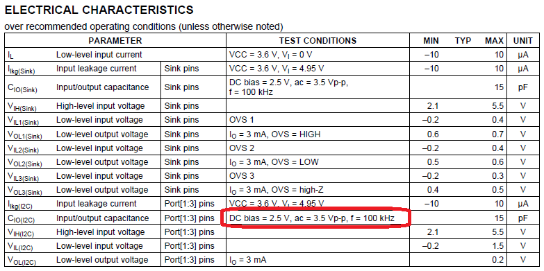
The maximum capacitance of DDC was not satisfied the HDMI compliance test specification version 1.4 if connecting the B-side ports to the HDMI connector.
As a result, it was ~nF order.
So, can TCA9517 be adapted for HDMI DDC ?

Best regards,
Kato

  • Kato-san,

    I am not familiar with the HDMI compliance test specification for 1.4. I assume you require a higher capacitance support.

    Typically, we've seen customers use the P82B96 or the P82B715 on high capacitance cables. The P82B96 supports 400khz and a capacitance up to 4000 pF.

    The P82B715 supports 100 khz and 300 kHz
  • Hi Jonathan-san,

    Thank you for your reply.
    Could you please provide me "the capacitance of A-side ports and B-side ports vs the freuency(100kHz to 1MHz)" if you have this information ?

    Best regards,
    Kato

  • Kato-san,

    Unfortunately, we do not have this data. The capacitance measurements were taken by hand at the test frequency only.

    A nF capacitance is very far outside of I2C spec, which leads me to believe this is a layout or measurement issue.
  • Hi Jonathan-san,
    Thank you for your quick response.
    I found that the test condition of maximum capacitance for the HDMI DDC is mentioned in the TMDS361B data sheet as below.
    By the way, have TCA9517 been adopted for the HDMI DDC repeater in the past ?
    Moreover, can both A-side ports and B-side ports be used for the HDMI DDC repeater in the viewpoint of the design ?
    Best regards,
    Kato
  • Kato-san,

    There have been some use cases of the TCA9517 in HDMI DDC. I have also seen the P82B96 used for DDC.

    Either A or B port can be facing the source or the sink. The direction does not matter if you are only using it as a repeated (VCCA == VCCB)
  • Hi Jonathan-san,

    Thank you for your advice.
    We will discuss this issue with our TI local office member and will contact you again.

    Best regards,
    Kato

  • Hi Jonathan-san,

    I have additional questions which I obtained from our customer.
    Could you please give me your advice as below ?

    Q1. Influence of the pull-up resistor value
    Does the value of the pull-up resistor influence the load capacitance ?

    Q2. Influence of the ripple voltage
    If the value of the pull-up resistor is small, does it influence the ripple voltage of the high level ?

    Best regards,
    Kato

  • Kato-san,

    1) This depends on the method of capacitance testing. Ideally, with a relatively high value resistor (4.7k+), that the capacitance should not change. There are a few different methods for measuring capacitance, and it is possible that a resistor in the path can change the value. This is more of a concern if your device measures capacitance based off measuring the RC time constant. Measuring S11 is one of the more preferred methods.

    2) I don't think I understand your question fully. Where would the ripple be coming from? Is this ripple from the power supply? If the ripple noise is from the power supply, then a lower-resistance resistor would decrease the RC time constant (and thus change the low pass filter cut off frequency), so it is possible that you'll see more ripple on the SDA/SCL lines if the ripple is relatively low frequency and rather large in swing. However, I would lean more towards saying that for most practical i2c resistor values and DC/DC switching frequencies, that this is not really a concern (typically the switching frequency is much higher than the I2C frequency)

  • Hi Jonathan-san,

    Thank you for explaining so politely.
    I understoot and will inform our customer of your advice.
    I greatly appreciate your cooperation.

    Best regards,
    Kato