This thread has been locked.

If you have a related question, please click the "Ask a related question" button in the top right corner. The newly created question will be automatically linked to this question.

On Board RS 485 communication

Dear All,

We are using ASIC that has internal RS485 transceiver but I need to manupulate serial data.

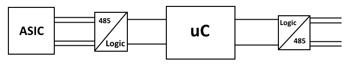
So I will use 2 transceiver;

 1. One for converting RS485 data to logic for data manupulation

2. One for converting logic to RS485 again to connect master application.

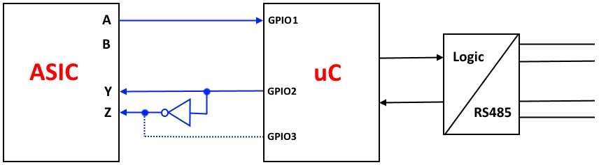
It is clear that I need to add termination / protection etc. for (2.) and I have done the second connection several time, But I never used RS485 for inter IC comm. in the same PCB and I just want to be sure if a termination resistor is actually required for (1.)

I can simply add a resistor and keep going, but it is a very small for factor device. More over ASIC RS485 driver diff output is 4V even with the 100mA current so very small size resistor is not appropriate. Also we need to keep current consumption lower. (Full dublex comm.)

Max. freq. will be 5 MHz and IC's will be 1 cm distance at max.  


What is your idea, can I simply omit termination resistors or do I need to simulate for SI ?

Does any one experienced such a stiuation ?

  • Yilmaz,

    Typically for high data rates termination is recommended, however your 1cm distance between devices is short enough that termination probably isn't required. In order for the transceivers to work properly, there are a couple of calculations to consider:

    - Assuming the velocity of the signal on the line is around 78% the speed of light, the propagation delay over the length of the cable (1 cm) will be around 43 ps
    - Typically reflections will settle out over around 3 trips across the line so the reflections should settle around .13ns
    - At 5Mhz, the bit time will be 100ns
    - The rise times for most RS-485 devices are greater than 2ns

    - Given that the device rise time and the bit time are much longer than the reflection lifetime, there shouldn't be an issue.

    Best Regards,
    Casey McCrea
  • Dear Mr. McCrea,

    I thank you for sharing your experiences.

    Best Regards.
  • Yilmaz,Do you know the unloaded RS485 single ended output voltage of the ASIC?
    You may be able to use just one of the RS485 signals directly or through a logic buffer.
    There is no need to use both output pins.
    Much cheaper and smaller than a RS485 chip for your 1 cm line.
  • Dear Mr. Michallick,

    In one application I have used only one of the driver diff ouput of the ASIC and it is compatible with TTL levels. But I need to drive 485 receiver differentially. So I need at least one diff. device for this. 

    ASIC diff. inputs are also TTL compatible, Maybe I could use 2 pins of uC to drive this. I will try and report result.

    Thank you for your time and interest

  • Dear Mr. Michallick,

    We have tried the scheme below and worked fine. All ASIC buffers are TTL compatible. 

    I just consult the ASIC manufacturer if I can omit NOT gate and use a second IO as a complementary output. Generic fast RS485 drivers has ~1ns skew for complementary outputs. But using microcontroller cause longer transition and asked for the max. permissible skew. 

    Best Regards.

  • Yilmaz,

    Input Z can be a DC signal halfway between the VOL and VOH of the GPIO2 signal.
    The voltage doesn't have to be exact. A resistor divider will work.


  • Dear Mr. Michallick,

    ASIC manufaturer has added a nice feature, it can be driven single ended if complementart input (Z) is connected to a capacitor.
    Now only one transceiver is enough.

    Thanks for support.

    Best Regards.