This thread has been locked.

If you have a related question, please click the "Ask a related question" button in the top right corner. The newly created question will be automatically linked to this question.

TCA9554 Standby Mode Current

Other Parts Discussed in Thread: TCA9554, TCA9534, TCA6408

Hi Sir:

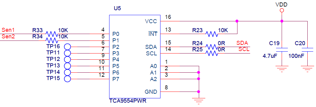
I have some questions about TCA9554.

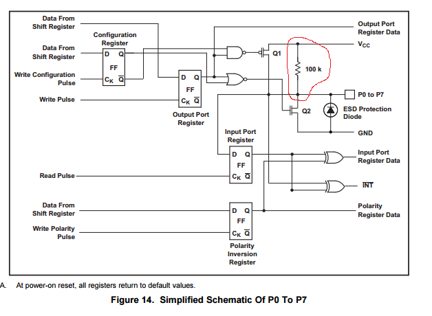
1. What mean "Standby Mode Current " as followings.

2. If I want to calculate power consumption. Does need to evaluate it?

3. If I need to setting minimum current and only use 2 port. (15uA per 1port)

    Can we disable other port current output?Because 15uA*8=120uA is too much for our application.

Thank you.

  • Hi Hugo ,

    I will initially move this into I2C forum.
  • The standby current is when the device is not clocked . during normal operation , the SCL input is clocked but I suspect that the standby mode current is having a typo of uA instead of uA.
    For your normal operation , you need to consider the Icc operating mode current and base your calculations on that . For any of the unused inputs , it is better to have it in a known state (Vcc or gnd ) instead of leaving it floating .
  • Thank you Shreyas,

    1) You are correct. However, during standby mode, the I2C bus is idle (FSCL = 0 Hz). All pins are in Input mode and at a known voltage (ground).

    2) If you'd like to measure power consumption, there are a few methods. You can estimate it based off the datasheet values for your given VCC and pin conditions. The more accurate way is to measure the current into the VCC pin and multiply it by Vcc (P = I*V).

    3) The best way to minimize power consumption on unused ports is to set them to inputs, and pull them to ground or VCC through a resistor externally.
  • Hi Sir:

    I have two questions about Q1 and Q3.

    1. We have set I2C, the chip isn't generate CLK signal.

    As you said,standby Mode and all pin are input and GND level.

    But we measure two output pin, the result is high. what is the reason?

    3. What mean 15uA ?  Is it per each port?  Is it total current consumption?

    Thank your support and help.

  • Hello Hugo,

    Could you explain a few things for me.

    1) If all pins are set to input mode and tied to ground, but you're measuring a non-ground voltage at the pin, what voltage are you measuring? One thing to note is that in this device, each pin has an internal pull-up resistor (100k). If absolute minimum power consumption is a careabout, then you will achieve better power consumption numbers by setting each port to an input mode, and pulling them up to Vcc (or leaving the pin floating, since the internal pull-up will pull it to Vcc).

    To answer your question 3) 15 uA is the TOTAL Icc flowing into the Vcc pin for the conditions described. In the line that you circled, it shows that all ports are set as inputs and are at either Vcc or Ground. It also states that this is with 0 current flowing into or out of pins. What this means, is that for 3.6V Vcc, you will need to add any additional current as a result of the port. For example, if you have an input, which is at 0V, then we'll have an additional 3.6V / 100k = 36uA of current flowing from Vcc through the pull-up resistor to ground.

    If you don't want any internal pull-up resistors, I would suggest looking at other 8-bit IO expanders without internal pullups.
    Some options:
    TCA9534[A]
    TCA6408
  • Hi Jonathan:

    Because We had measure system power consumption is 670uA.

    After I remove R33 and R34 (TCA9554 output pin) as followings, power consumption become 390uA.

    That the TCA9554's power consumption about 280uA.

    May I know what is causing too much power consumption? Thank you.

  • Hello Hugo,

    The reason removing R33 and R34 dropped your power consumption, is because putting a 10k series resistor with the internal 100k pull-ups resulted in a voltage divider. Depending on the input voltage, your actual voltage at P0 and P1 would be somewhere in between gnd and VCC, which causes excessive leakage in the cmos setup (the NMOS and PMOS are both slightly turned on, causing the extra leakage).

    This is why it is important that whatever you is supplying SEN1 and SEN2, have enough drive strength to sink the 100k pull-up current. You really want to the input voltage from Sen1 and Sen2 to be either 0 V or Vcc, anything in between will result in excessive leakage.

    Please also note that when any input is at 0V, there is the 100k pull-up resistor to Vcc internally. This will result in an additional Vdd/100k of current.
  • Please look at the port schematic below, to see the source of this additional current.

    As I had mentioned earlier, if you do not need this internal pull-up resistor, you might want to look at the TCA9534, since it is also an 8 bit IO expander, but without the internal pull-up resistors.