Because of the Thanksgiving holiday in the U.S., TI E2E™ design support forum responses may be delayed from November 25 through December 2. Thank you for your patience.

This thread has been locked.

If you have a related question, please click the "Ask a related question" button in the top right corner. The newly created question will be automatically linked to this question.

SN65HVD1780 RS-485 Application Issue

Other Parts Discussed in Thread: SN65HVD1780

I have an application whereby an MCU is controlling a SN65HVD1780 on a RS485 network bus with another device.  The DE and ~RE lines are connected together and they are controlled by the MCU.  It appears that after a transmission has completed and the MCU transitions the DE/~RE lines low that the Receive line transitions from high to low prematurely causing the UART on my MCU to thank it has received a start bit which causes a framing error.  It’s as if the Fail Safe Receiver for Idle-Bus Conditions is not keeping the state of the receive output line in the high state until the other controller can drive the differential lines to respond to the transmission.

Have you ever seen this before?

Are you aware of any issues with driving the DE and ~RE lines of the SN65HVD1780 together without a pull down resistor connected to the lines?

  • Hi Tim,

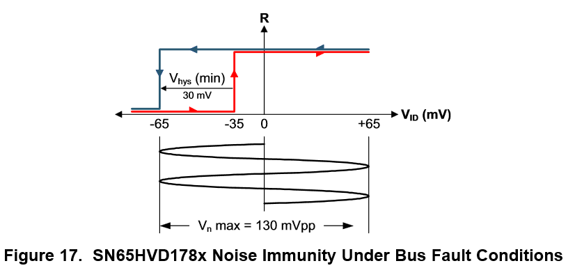
    There should be no premature transition with the internal fail safe biasing circuit. I would like to see a screen shot of the A/B pins, the /RE and DE pins, as well as the R output. My guess is that you are violating the failsafe requirements below:

    I suspect that there is either a timing issue on the D pin where you have not allowed for enough delay in between disabling the driver and enabling the receiver that is causing the receiver to see a voltage that is violating the above picture or there is simply a differential voltage that exists on the bus when you are making the transition that is causing the unwanted output on R. I think that looking at the above mentioned signals simultaneously on a scope will show us more about the problem.

  • Michael,


    Can you verify the signal logic for this chip for me?

    I have attached a logic analyzer output for your reference.

    The transceiver differential line states are shown on probe 4 and 5 labeled '485+' and '485-' respectively.  The receiver output is shown on probe 0 labeled 'RX Isolated'.  The receiver enable is shown on probe 1 labeled '!RE/DE'.

    There is nothing driving the 485+ and 485- differential lines on this bus so it is an Open-circuit bus.  According to the logic analyzer output the differential lines are both logic high.  Is this what they should be?

  • Hi Tim,

    Your image did not come through but I think I understand what you are describing without the image.

    The input stage of an RS-485 devices includes an attenuation stage which allows the device to support wide input common mode rages and it looks something like this:

    As you can see the attenuation stage is biased to some voltage that is determined by the value of R2 and R3, In the case of the SN65HVD1780 this bias voltage is typically Vcc/2 for a stand alone device. But if you were measuring this on a device that was connected to a bus that had some number of nodes on it this voltage can droop depending on the leakage current at each node.

    When using a logic analyzer to determine the state of the A/B pins the result will be a combination of the voltage at the pins and the threshold levels set on the logic analyzer. If the measurement is being done on a stand alone device where the pins are being biased to Vcc/2 and the threshold level is set to value less than this value than you should record a logic high like you are currently seeing.


    Does this help? If not let me know and we will continue to chase down a solution for you! Also attached is a presentation that my team and I have given at tech days around the world regarding RS-485. It has lots of useful information and I will be more than happy to address any questions you have regarding any of the content.

    RS-485 Industrial Workhorse's Design Guide and Crash Course.pdf