This thread has been locked.
If you have a related question, please click the "Ask a related question" button in the top right corner. The newly created question will be automatically linked to this question.
first question
There is a controller that has the first of many in series. This controller talks to a slave "motor base" MSP430 and a second 9517A which then passes the data to another "motor base" and 9517A etc...... This is a series connection to send messages in a string about 20 bases long.
Second concern Communication polling is only about 10 times a second.
On the third point we have disconnected the "controller daughter card" from all bases and with the pullup on side B still engaged and a high on side B SCL the A side SCL is pulled low unless we disable the chip. We cut the trace to the enable line in the schematic and installed a 4.7K resistor so we could force the EN low. When low we see the clock signal on the A side again.
Replacing the chip seems to correct the problem but we are concerned about the failure. This has happened on three out of 10 devices. We do not seem to see this behavior on the motor bases (same circuit) but we have only built up about 20 of these so far. Early on we did replace some 9517A's on the motor bases but this was early on in the Firmware development and we cannot be sure if there were firmware issues or part issues at that time.
Thank you for the information.
I'm not sure what could cause a failure like this other than some sort of electrical over stress condition. Are there are switching transients? Or transients from the motor?
It is possible to damage the device if the source current is too much (IE, you force the 9517 to sink a significant amount of current, enough to damage the internal pull-down FET.
Your pull-up resistors look appropriate, though. Can you verify the current flowing into the SDA/SCL pins on the side that is not being forced down? For example, if the master is transmitting a 0 on the A side, then the 9517 will sink current on the B side to repeat the 0.
You also mentioned that you had a change in firmware? I would agree that I don't think a change in firmware would cause a hard failure.
When you test your failed units, the A side is permanently stuck low unless you pull the EN line low? Correct? It will not behave normally once damaged, even if you test it by itself?
EoS was my first thought but we do need to be able to disconnect the controller from the string of motor bases in maintance situations (rare cases) but I would suspect that this would damage the B side as that is the side on the controller that faces the connection, but it seems the A side is faulty.
As for motor transient the motor is a low power (< 5 watt) synchronous AC 120V type that has optically isolated control. The logic power for the board is well isolated and protected away from the motor AC. This AC power does not even run in the same bundle as the DC/control cable.
We can look into the current draw but the only connections on the I2C is the B side of the input 9517A, the MSP430 slave and the A side of the output 9517A
as for the pullups the 20K on the output B side are there so that the last device in the chain has something to work against in the bulk of the devices in the string the 20K is in parallel with a 10K on the input side of the next for a total of 6.7K which I thought was a fair compromise at these logic levels.
All the firmware updates have allowed for longer more robust communication along the I2C chain.of course we are working on other functionality as well and some of these changes have effected the I2C communication but not to the extent that when we disconnect downstream devices the SCL gets stuck low on the controller daughter card ( the first 9517A in the chain.). We do not see the downstream devices effected in this way up to now.
As for the last statement we have not been able to recover a device after the problem has occurred, only a device replacement seems to help.
Dante
Ok, thank you.
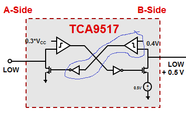
That is what I find interesting. The fact that pulling the EN pin low puts the IC into high impedance sucesffuly and then releasing it (if the B side is at a high voltage) causes the A side to immediately go low. It would appear that there is some damage to the internal logic gates (possibly the internal comparator on the B side, which is responsible for activating the A side pull-down FET).
I'm just throwing some thoughts out, since this is an issue I've not encountered before.
Take a look at the example block diagram of the part below (the TCA and PCA9517 are very similar, except that the TCA is newer, and supports lower voltage, and has some improved design parameters).
There is additional gate which acts as an 'and' gate with the EN pin. Since the EN pin appears to function correctly, I don't think the damage is occurring to the pull-down FET on the A side, but perhaps the B-side comparator, always thinking a low is being transmitted.
Is there any chance of an EOS being applied to the B side? a TVS might work, so long as you make sure capacitance at your I2C frequency is low enough and the clamping voltage is fairly low too.
Jonathan,
Thanks for all your help (and the rest of the team there at TI)
So far so good on the TVS diode, We seem to have eliminated the issue for now.
Dante