This thread has been locked.

If you have a related question, please click the "Ask a related question" button in the top right corner. The newly created question will be automatically linked to this question.

TLK105L ESD Issues

Other Parts Discussed in Thread: TLK105L

We are using the TLK105L part on a design with an IMX6 processor running Linux with Freescale’s provided generic 802.3 driver. Recent ESD testing with an unshielded cable has shown a previously undiscovered problem where the link will go down and not come back up again. This happens at Air ESD levels as low as +6kV. Only happens at + for some reason. No discharge actually takes place, just having the static field present near the cable causes the problem to manifest.  I have direct register access and I was able to identify 2 failure modes.

  1. Phy gets stuck in MII mode instead of RMII mode. Register 0x17 is reads 0x0061 when working properly and 0x0041 after the ESD event. Writing the register back to 0x0061 has no effect. Toggling the hardware reset line causes this register to come back to 0x0061. My best guess is the PHY is resetting and not sensing the MII_MODE pin properly during power-up. This operation is not desirable, but at least its detectable and it can be remedied with software polling register 0x17 and toggling the reset line. Some register setup is also required after the reset, I can share that detail if you like.
  2. Phy gets locked continually changing between MDI and MDI-X mode. Read register 0x13 and see it’s a 0x0800 every time its read. It’s supposed to clear to zero after a read, but this interrupt flag is constantly set in the fault condition. This is the same result as if there is no cable connected, so it may not mean anything. Either way, the link is down and toggling the reset line does NOT bring it back. The PHY has not been damaged as far as I can tell since a reboot of the entire system does bring it back.
    Things I tried that didn’t help:
    1. Setting the bit that restarts Auto-negotiation.
    2. Setting register 0x17 to 0x0041 and then back to 0x0061 to hopefully re-init the RMII link.
    3. Disabling the Auto MDI/MDI-X and manually setting it one way or the other.
    4. Writing register 0x1F to 0x0040. It’s a reserved bit but I see it set sometimes and not others.
    5. Writing register 0x1F to either 0x8000 or 0x4000 to accomplish internal resets.


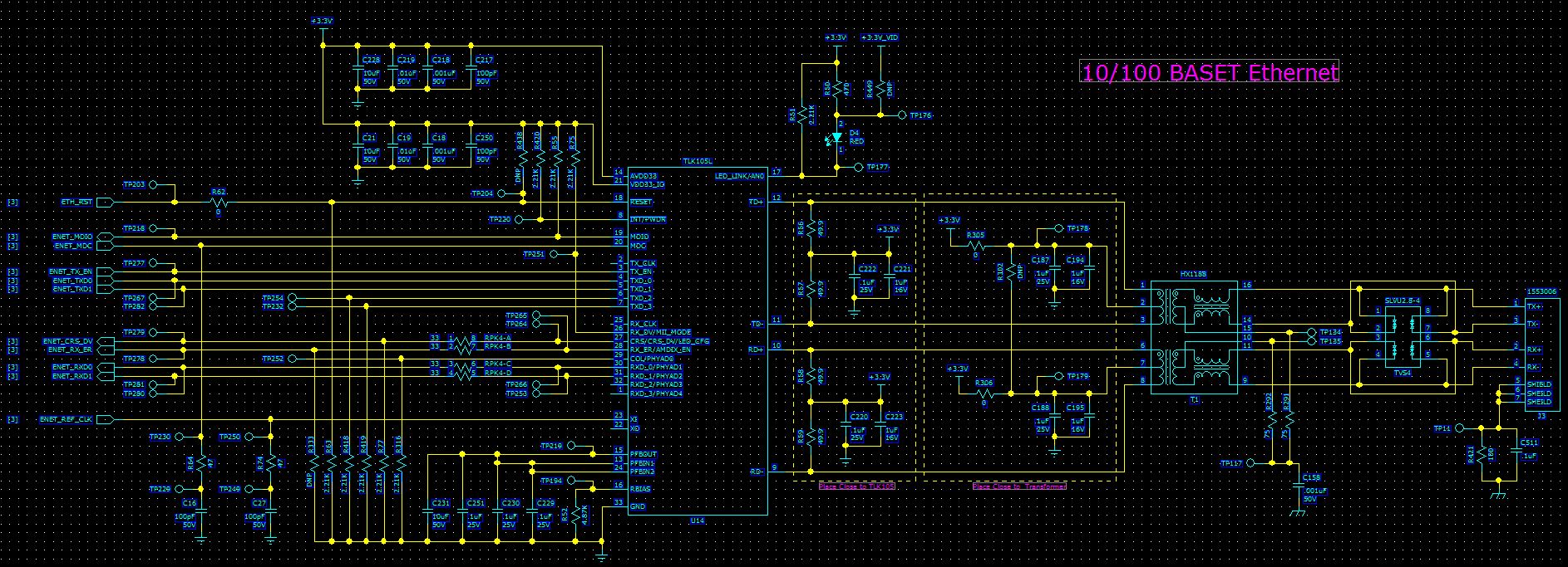
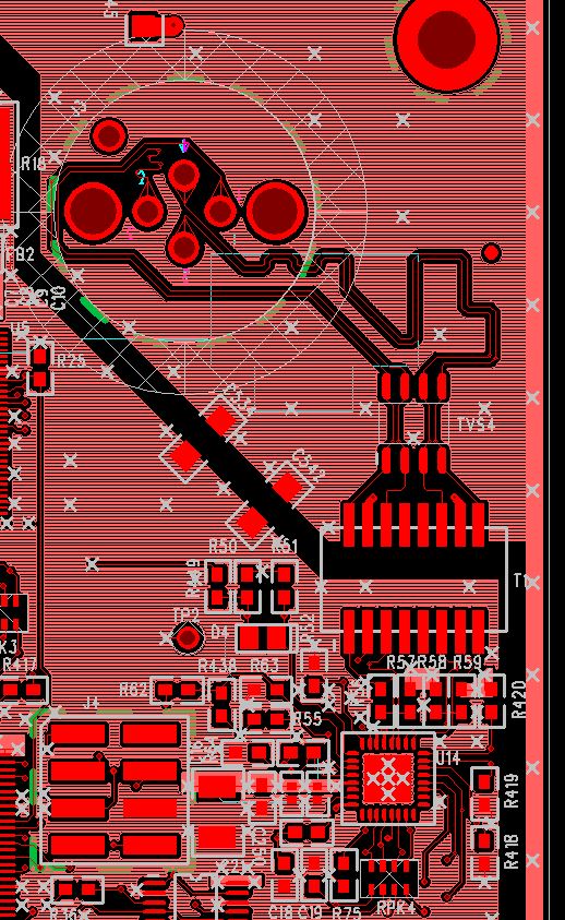
I made some quick screenshots of the schematic and layout since those are usually the first questions. The layout just shows the top layer, but it’s a 10 layer PCB. The connector is an M12 circular industrial Ethernet. As you can see there is a large gap between the plane where the connector is at and the plane the PHY references. At the moment we are trying to make software changes only since the design is frozen. It’s totally fine if the PHY resets and relinks. The trouble is when it gets stuck and requires an entire system reboot to come out of it. It’s really strange that toggling the PHY reset line does not accomplish the same thing as a system reboot in the case of the 2nd failure mode.


Here are the first 32 registers after the ESD event causes it to get into the 2nd failure mode. I did note some of the reserved registers were not at the default state, if that means anything.


Any clues or things to try would be greatly appreciated. Thanks for your help.

  • You have done some good analysis and provided lots of good information here.

    For the first case, I suspect you are correct. The PHY may be getting reset and inadvertently strapped to MII mode.

    The functionality you are seeing in the second case is not as clear to me. The toggling between MDI and MDIX modes is a normal part of link establishment when using auto-negotiation. I would expect you to see a similar toggling between MDI and MDIX in the PHYSTS register (address 0x10). I'm not sure why this functionality is not affected by toggling the reset pin. I will look into this.

    In the meantime, could you provide some additional information on the registers that you provided for the second case? Were these captured before or after toggling the reset pin? It would be good to see the registers in both cases. It would be best to provide two consecutive reads of the registers in both cases. Some of the register bits latch their status so a second read will provide a current status.

    Patrick
  • I've got a bit more information.  Here are the registers prior to toggling the reset line.

    Address 1st Func Read 2nd Func Read 1st Read Mode 2 2nd Read Mode 2
    0x00 0x3100 0x3100
    0x01 0x786D 0x7849
    0x02 0x2000 0x2000
    0x03 0xA212 0xA212
    0x04 0x05E1 0x05E1
    0x05 0x4421 0x0000
    0x06 0x0007 0x0005 0x0006 0x0004
    0x07 0x2001 0x2001
    0x08 0x0000 0x0000
    0x09 0x7800 0x7800
    0x0A 0x0104 0x0104
    0x0B 0x1000 0x1000
    0x0C 0x0000 0x0000
    0x0D 0x0000 0x0000
    0x0E 0x0000 0x0000
    0x0F 0x0000 0x0000
    0x10 0x1813 0x1802 0x5802 Alternates between the two states
    0x11 0x0108 0x0108
    0x12 0xFE00 0x0000 0x2000 0x0000
    0x13 0x2A00 0x0000 0x0800
    0x14 0x0000 0x0000
    0x15 0x0000 0x0000
    0x16 0x0100 0x0100
    0x17 0x0061 0x0061
    0x18 0x0400 0x0400
    0x19 0xB000 0x8000
    0x1A 0x0010 0x0000 0x0010 0x0000
    0x1B 0x007D 0x007D
    0x1C 0x05EE 0x05EE
    0x1D 0x0000 0x0000
    0x1E 0x0002 0x0102 0x0102
    0x1F 0x0040 0x0040

    This is after toggling the reset line

    Address 1st Func Read 2nd Func Read 1st Read Mode 2 2nd Read Mode 2 1st Read after Reset 2nd Read after Reset
    0x00 0x3100 0x3100 0x3100
    0x01 0x786D 0x7849 0x7849
    0x02 0x2000 0x2000 0x2000
    0x03 0xA212 0xA212 0xA212
    0x04 0x05E1 0x05E1 0x01E1
    0x05 0x4421 0x0000 0x0000
    0x06 0x0007 0x0005 0x0006 0x0004 0x0005 0x0004
    0x07 0x2001 0x2001 0x2001
    0x08 0x0000 0x0000 0x0000
    0x09 0x7800 0x7800 0x7800
    0x0A 0x0104 0x0104 0x0104
    0x0B 0x1000 0x1000 0x1000
    0x0C 0x0000 0x0000 0x0000
    0x0D 0x0000 0x0000 0x0000
    0x0E 0x0000 0x0000 0x0000
    0x0F 0x0000 0x0000 0x0000
    0x10 0x1813 0x1802 0x5802 Alternates between the two states 0x5002 0x1002 Alternates between the 2 states.
    0x11 0x0108 0x0108 0x0108
    0x12 0xFE00 0x0000 0x2000 0x0000 0x0000
    0x13 0x2A00 0x0000 0x0800 0x0A00 0x0800
    0x14 0x0000 0x0000 0x0000
    0x15 0x0000 0x0000 0x0000
    0x16 0x0100 0x0100 0x0100
    0x17 0x0061 0x0061 0x0061
    0x18 0x0400 0x0400 0x0400
    0x19 0xB000 0x8000 0x8000
    0x1A 0x0010 0x0000 0x0010 0x0000 0x0010 0x0000
    0x1B 0x007D 0x007D 0x007D
    0x1C 0x05EE 0x05EE 0x05EE
    0x1D 0x0000 0x0000 0x0000
    0x1E 0x0002 0x0102 0x0102
    0x1F 0x0040 0x0040 0x0000
  • Patrick, did you have any further feedback on this?
  • Mike,

    In looking at the register information, it does not appear to show the issue of getting stuck in MII mode. The issue now appears to be a matter of establishing link.

    Based register 0x10, the PHY appears to be trying to link in 10M mode. How is the link partner configured in this case? Is it auto-negotiating?

    I see that register 0x1F is set for 0x0040 in some cases. Are you writing to register 0x1F?

    Patrick
  • The register information sent was not intended to show the first failure mode (getting stuck in MII mode). It was to demonstrate the 2nd failure mode where ESD caused it to drop the link and not re-establish, even after toggle of the hardware reset line. The device had to be fully powered off to recover.

    Yes, the PHY is in 10M link mode. The link partner is set to allow all modes, with Auto-negotiation enabled.

    We are not writing to register 0x1F. I had also noticed that it shows 0x0040 in some cases, but since it’s in reserved locations I have no idea what it means.