This thread has been locked.

If you have a related question, please click the "Ask a related question" button in the top right corner. The newly created question will be automatically linked to this question.

How should Y and Z behave after Hi-z?

Other Parts Discussed in Thread: SN75LBC172

Dear Technical Support Team

I have a question about SN75LBC172. 

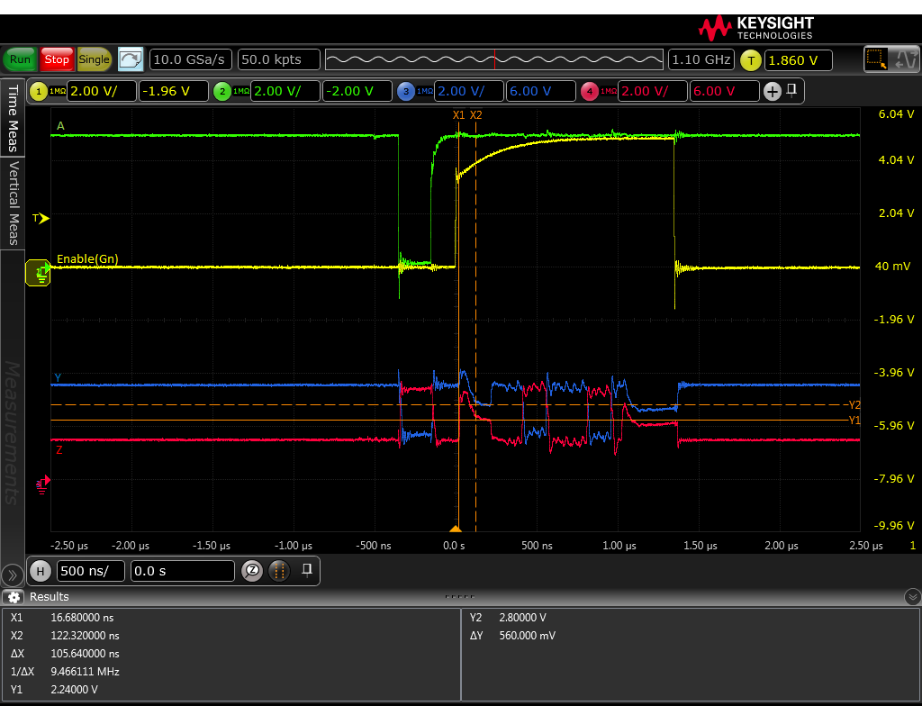
Following is a waveform on Osillospcope.

Y and Z drive high(between cursole X1 an cursole X2) at the same time after an enable(Gn) is high(Enable(G) tied GND).

After that these levels fall down slowly and keep immideately dividing voltage level(①:2.78V / ②:2.22V) depended on register

Is it the correct operation for Y and Z?

I think that Y and Z are Hi-z and these volatage shows immideately dividing voltage level(①:2.78V / ②:2.22V).

5V - 390Ω- 100Ω- 390Ω- GND

          ↑      ↑

         ①Y      ②Z

Best Regards,

y.i

  • Y.I.,

    Yes, you are correct. When the driver is disabled, the Y and Z outputs will both be high-impedance. This means that their voltages will be set by the external termination network that you described (which configures VY = 2.78 V and VZ = 2.22 V). Both signals seem to go high immediately after the disable signal is sent. This is because the low side of the signal becomes high-impedance slightly faster than the high side (as shown in the tPHZ and tPLZ specifications). As soon as the lower side goes high impedance, it becomes pulled up the the high level through the 100-Ohm termination resistance.

    I hope this info is all clear; please let me know if you have any other questions.

    Max