This thread has been locked.

If you have a related question, please click the "Ask a related question" button in the top right corner. The newly created question will be automatically linked to this question.

TPD12S520 resistance between GND and ESD_BYP

Other Parts Discussed in Thread: TPD12S520

Is the device blown out if the resistance is very low as to trigger beep on continuity detector (<5Ohm)? 

This device seems to have worked fine but then it started blocking the LV translated signals, making them 0.7V instead of 3.3V as they were on the ASIC side, and the same on the output. My LV_SUPPLY is 3.1V (which is the 3.3V after the 10K resistor) and 5V_SUPPLY is connected directly to 5V rail of device.

  • Hi Rajko,

    This product belongs in the ESD forum.  I will go ahead and move this post.

    Thanks,

    Alek Kaknevicius

  • Rajko,

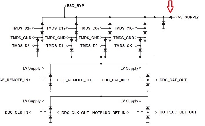
    There should be high impedance between GND and ESD_BYP, if you are seeing less than 5 ohms then the device has been damaged.
  • By what ? I thought this was supposed to protect against ESD, it worked on my board for a while, then i just plugged in HDMI once and there was a short between 5V and GND because something blew the 5v sense on my ADV7611 and apparently the ESD protection chip.
  • Can I see a schematic?
  • Rajko,

    Let's be certain about the continuity tester, if it applies more than about 0.7 V then the diode I point to below will be conducting, and 5 ohms sounds about right. I do believe that continuity testers apply a voltage. I recommend measuring  with an ohmmeter, it should be high impedance (mega-ohms). Please let me know how that looks.

    Thanks,

    Guy

  • No it was an Ohm-meter that can read megaohms.

    I think the whole thing is blown, as well as the entire input block of the ADV7611, somehow, i might have shorted something while i was testing the pins for voltage as it was running. The HDMI pins should be straight-through, but they are high impedance as i test them now.

    Also, the TI ESD device was running for a while with 5V not connected (but LV was connected) before i realised it, maybe that blew something ?

    The schematic is as here: https://github.com/esar/hdmilight-v2/tree/master/board


    But i used 2 BSS123LT1G instead of FDY3000NZ, maybe that was a problem too ?

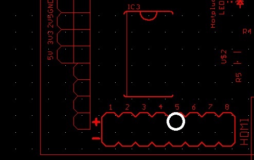
  • There should be no problem running it without 5V connected. It looks like the 5V_SUPPLY pin is connected to a connector (white circle shown below). It's likely that ESD (or maybe the cable was charged and discharged upon connect) damaged the TPD12S520 when that cable was attached, as the 5V_SUPPLY pin is not intended to be connected to an ESD source. That pin, and LV_SUPPLY, CE_REMOTE_IN, DDC_CLK_IN, DDC_DAT_IN, and HOTPLUG_DET_IN are only rated +/- 2-kV ESD.

  • Got another couple of TPD ESD chips, are the 'straight-through' pins on the TSSOP38 supposed to be connected on the pcb ? The chip itself should conduct through them, right ?

    Because this is what my pcb is: images.sshnuke.net/2015-12-14_21-55-28.png
  • Also, the first time i powered up a newly soldered TPD, ESD_BYP is now directly connected to 5V_IN, on the spare new one i have it behaves like a diode.
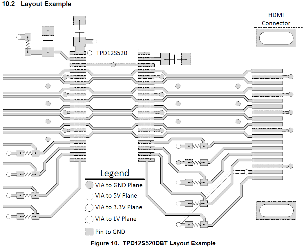
  • Please follow the layout guide from the data sheet:

    The data lines route underneath the device. In your layout they do not.

    Regarding the behavior between the ESD_BYP pin and 5V_SUPPLY on-board and off, where on-board they are shorted and off-board the diode is visible between them, I would want to know if there is any resistance between the board's ESD_BYP and 5V_SUPPLY pins on an unpopulated board as your description indicates there is not.

  • No, my ESD_BYP is there only for the capacitor: images.sshnuke.net/2015-12-15_20-48-19.png
    I'm asking since the first time i powered the board up, that measured 4.3V, now it measures 5.3 and is 0ohm to 5V_supply. Did it somehow break even though i never connected anything to the hdmi port ?

    So, if the 2 data pins opposite each other are not connected... why does the pdf give them the same net name :( These boards are useless now, i would have to solder mini bodge wires across the chip to get hdmi going. In other ESD products, the pdf clearly says the 'output pin' is NC, like this: www.semtech.com/.../rclamp0522p_0524p.pdf

    Guess i should have read the tiny (4) footnote.
    I made another schematic since you said the last one wasn't connecting 5V properly: files.sshnuke.net/MainSch.pdf , is the TPD properly supplied now ?
  • Sorry about your board. In the Pin Description we clearly note for any pin named TMDS_D2+ (for example) these two pins must be connected together inline on the PCB. We also show this in the layout example.

    Can I know what is the resistance between the unpopulated board's SMD pads for ESD_BYP and 5V_SUPPLY?
  • Just desoldered the TPD, with it off, the resistance is infinite as it should be per schematic (ESD_BYP is only there for the capacitor link to ground).

    Testing the TPD on its own shows 1Ohm between 5V_SUPPLY and ESD_BYP, and the votlage drop in diode mode 0v, so somehow the diode got blown ? My other spare TPD have the resistance there infinite and the voltage drop 0.6/0.7v.

    This is the 2nd TPD that got damaged very shortly after being installed on the board, this time even without plugging the hdmi jack in !

  • Hello,

    Regarding your question about the 5V_SUPPLY pin connection to the 5V rail in the new schematic, it is correct.

    Thanks for checking the board out. Did you test this TPD12S520 before soldering it to the board? The cause of this problem is very elusive, it is the first problem of it's type with this device and so far it is not making sense to me. To recap the problem description: The TPD12S520 diode drop between 5V_SUPPLY and ESD_BYP is visible before soldering it to the board, and after soldering it to the board it behaves as a short. Is this correct? What if we solder the TPD12S520 to the board and measure between the two pins before powering on the board?

    Regards,

  • You misunderstood.The TPD 5V diode got blown very shortly after the board was powered up, its not a matter of it being on the board or not. That chip is now permanently like that, off board or on.

    Weirdly, no HDMI cable was ever connected to that chip for it to blow.

    A new chip has been placed on the board and the readings are now correct, let's see how long it lasts.

  • Hello Rajko,

    The only things I can think of that can cause this issue is the voltage on 5V_SUPPLY is exceeding 6-V (the abs-max). Can you try monitoring the 5V_SUPPLY pin with an oscilloscope, triggering on 5.9 V? 

    Regards,

  • It's running fine now on the same board, new TPD.

    Must have shorted all the other ones somehow.