Because of the Thanksgiving holiday in the U.S., TI E2E™ design support forum responses may be delayed from November 25 through December 2. Thank you for your patience.

This thread has been locked.

If you have a related question, please click the "Ask a related question" button in the top right corner. The newly created question will be automatically linked to this question.

TPD12S520 - HPD Design Change

Other Parts Discussed in Thread: TPD12S520, TPD1E05U06, TS5A3166

Hi,

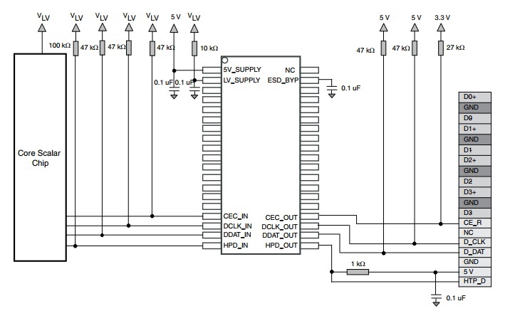
We are using the ESD protection & level shifting device - TPD12S520 in the HDMI input path of one of our boards. We have done the TPD12S520 design as per the receiver side application schematic provided in the datasheet (snapshot provided below for reference). Note that we have used LV supply of 3.3V.

Here the HPD_OUT (hot plug detect) pin of TPD12S520 is pulled-up to 5V HDMI using 1k resistor near the HDMI connector. So as soon as the HDMI source is connected, the HPD will be asserted (driven high) to the source. This will happen even if the board is powered OFF.

This condition is creating issues in our testing and results in the  video standard change of the HDMI source. So to avoid this problem, we are planning to remove the 1k pull-up resistor on the HPD pin at the connector side and also change the 100k pull-up to 1k on the HPD_IN pin on the HDMI receiver IC side.Note that as per the HDMI specifications, the source should have around 10K pull-down on the HPD input.

By doing these changes, the HPD output will be low when the source is connected with board powered OFF and will be asserted only when the HDMI receiver IC is powered ON & active.

Kindly let us know if these changes can be made in the TPD12S520 schematic.

Regards,

Elvin

  • Hi Elvin,

    Your solution should work with any source, hub, re-driver I can think of. One thing to be concerned about is terminating the 5V pin on the HDMI connector, a 2K resistor should be fine. Floating pins can cause problems, see: Preventing ESD Arcing in a Connector

    Regards,

  • Hi Guy Yater,

    We have connected the 5V pin of the HDMI connector to the 5V detect pin of the HDMI receiver IC. In addition there is also 0.1uF decoupling capacitor on this pin. So this pin is not left floating. Do you still see any issue and suggest to terminate this pin with 2K resistor?

    If so, we can replace the 0.1uF capacitor with 2K resistor. Can we do this change?

    Regards,
    Elvin
  • Hi Elvin,

    If you need the 5V pin of the HDMI connector to be connected to the 5V detect pin of the HDMI receiver IC, then I would suggest using a TVS to protect the IC from any ESD on that line. TPD1E05U06 is my recommendation. If the 5V detect pin does not need to see the 5V pin of the HDMI connector, then a 2K resistor to ground would give a path to ground for any ESD on that pin and only sink 2.5 mA from the source.

    Regards,
  • Hi Guy Yater,

    Thank you for the information.

    I have one more query regarding TPD12S520.

    What is the recommended 5V_SUPPLY to this device? - 5V generated on the board or HDMI connector 5V supply

    Currently we have used the 5V generated on the board.

    Regards,
    Elvin
  • Hi Elvin,

    As long as it can supply 5 uA it should not matter, but our data sheet uses an on-board supply.

    Regards,

  • Hi Guy Yater,

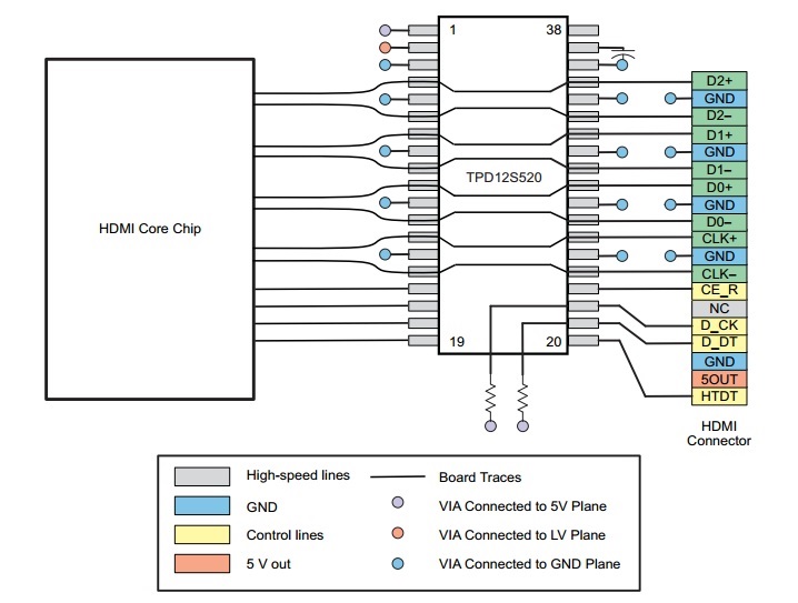
    The TPD12S520  datasheet uses 5V HDMI from the connector. This can be seen in the snapshot of the application schematic which I had provided before and also in the below snapshot of the TPD12S520 layout.

    Now if the 5V HDMI is connected to the 5V_SUPPLY pin of TPD12S520, then there will be ESD protection on this signal. In this case, do we need to provide additional ESD device on 5V HDMI signal which is also connected to the detect pin of the HDMI receiver IC?

    Regards,

    Elvin

  • Hi Elvin,

    I am glad you bring this up. The 5V_SUPPLY pin (Pin 1) is meant to only be connected to a 5-V power rail on the PCB. It has only been designed to withstand 2-kV of ESD, not 8 kV as the connector pins are designed to withstand.

    Yes, the 5V HDMI signal should have a TVS if it is connected to the receiver IC. I recommend TPD1E05U06.

    Regards,
  • Hi Guy Yater,

    Thank you for the clarification.

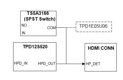
    We are checking the feasibility of implementing a circuit on our board that could prevent assertion of HPD to the HDMI source when board is powered OFF. I have shown below a part of the circuit which we are planning to implement.

    The HPD_OUT pin of TPD12S520 can withstand 8kV ESD. However the SPST switch-TS5A3166  can withstand only 2kV ESD. In this case, do you recommend to add additional ESD protection (shown in dotted lines) at the COM output of the switch?

    Regards,

    Elvin

  • Hi Elvin,

    You do not need to provide additional ESD protection for the TS5A3166. I would recommend adding some distance between the TS5A3166 and the TPD12S520, which is a typical arrangement recommended like this: connector -> (short distance) -> TVS -> (maximized distance) -> Protected IC. There is no recommended distance for "maximized distance," just let your board constraints be the dictator and keep as much distance between your protected IC and the TVS as allowed. Also, make sure that the HPD_OUT pin is placed in the direct path (not "T-eed" in or a stub) between the HPD_Connector and TS5A3166. More information is available in my ESD Layout Guide.


    Regards,