This thread has been locked.

If you have a related question, please click the "Ask a related question" button in the top right corner. The newly created question will be automatically linked to this question.

Reg:PCA9306IDCURQ1 power up requirement

Hi ,

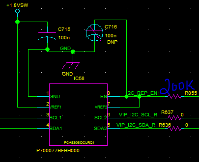
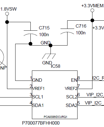
I am using PCA9306IDCURQ1 in my design for the I2C voltage level translation application, it is interfaced in my circuit as shown in the below image: Enable pin I am controlling from my reset controller, is there any issue in this circuit ? because in data sheet application regarding bidirectional voltage level translation application it shows that both en & vref2 are tied together connected to 3.3V supply using 200K resistor is it required in my case also ? Anyone Pls clarify ?

Regards,

Rajesh

  • Hello Rajesh.

    Please view the data sheet typical application section. I would suggest looking at the non Q1 data sheet, since it is has some more information.

    There is a typical application diagram showing how you to connect the device for translation.

    Your current set up will not do voltage translation. The VREF2 pin and the EN pin should be shorted together and then pulled up to your 3.3V rail by a 200k resistor. If your enable signal is 3.3V, you can pull the shorted EN/VREF2 up to your EN pin and use that to control whether the device is on or off.
  • Hi,
    Thanks for the reply, As per your suggession I will short both enable & vref as shown in the application circuit & it will be controlled from the 3.3V logic controller.

    In this I have few quries:
    1. In Vref2 how much current it will sink from the controller ?
    2. if any one Vref is a not available, then the device will be in high impedance at both the side?

    Regards,
    Rajesh
  • Rajesh,

    You should use a pull-up resistor (series resistor) to your controller from the shorted EN/VREF2 node. The value is 200k ohms. You can see an example in the data sheet. Instead of connecting it to a power rail through the resistor, you connect it to your micro controller through the resistor.

    The load is going to be the following:
    ICC(VREF2) = [VREF2 - (VREF1 + 0.7V)]/200k (your series resistor value)

    If you would like me to review your revised schematic, I can do that for you.

    As a note, you do not need decoupling on the VREF2/EN node. It will slow down your response rate when you disable your EN signal from the micro controller (slow to turn off)
  • Hi,

    I had updated the sch accordingly, Pls find the snap below: pls provide your feedback on the same:

    Regards,

    Rajesh

  • This looks correct.

    I assume you have the 3.3V signal from your micro controller connected to the right side of the 200k resistor? If so, then you're correct.